WOLFRAM SYSTEM MODELER
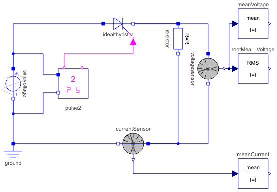
Thyristor1Pulse_ROne pulse rectifier with resistive load and constant firing angle |
|
Diagram
Wolfram Language
In[1]:=
SystemModel["Modelica.Electrical.PowerConverters.Examples.ACDC.Rectifier1Pulse.Thyristor1Pulse_R"]
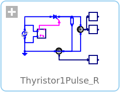
Out[1]:=
Information
This information is part of the Modelica Standard Library maintained by the Modelica Association.
This example demonstrates the operational behavior of a single-phase controlled rectifier with constant firing angle and resistive load.
Plot current currentSensor.i, average current meanCurrent.y, voltage voltageSensor.v and average voltage meanVoltage.v.
Parameters (4)
| Vrms |
Value: 110 Type: Voltage (V) Description: RMS supply voltage |
|---|---|
| f |
Value: 50 Type: Frequency (Hz) Description: Frequency |
| constantFiringAngle |
Value: 30 * pi / 180 Type: Angle (rad) Description: Firing angle |
| R |
Value: 20 Type: Resistance (Ω) Description: Load resistance |
Components (10)
| voltagesensor |
Type: VoltageSensor Description: Sensor to measure the voltage between two pins |
|
|---|---|---|
| sinevoltage |
Type: SineVoltage Description: Sine voltage source |
|
| ground |
Type: Ground Description: Ground node |
|
| currentSensor |
Type: CurrentSensor Description: Sensor to measure the current in a branch |
|
| meanVoltage |
Type: Mean Description: Calculate mean over period 1/f |
|
| rootMeanSquareVoltage |
Type: RootMeanSquare Description: Calculate root mean square over period 1/f |
|
| meanCurrent |
Type: Mean Description: Calculate mean over period 1/f |
|
| pulse2 |
Type: VoltageBridge2Pulse Description: Control of 2 pulse bridge rectifier |
|
| idealthyristor |
Type: IdealThyristor Description: Ideal thyristor |
|
| resistor |
Type: Resistor Description: Ideal linear electrical resistor |