WOLFRAM SYSTEM MODELER
Thyristor1Pulse_R_CharacteristicControl characteristic of one pulse rectifier with resistive load |
|
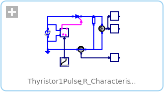
Diagram

Wolfram Language
In[1]:=
SystemModel["Modelica.Electrical.PowerConverters.Examples.ACDC.Rectifier1Pulse.Thyristor1Pulse_R_Characteristic"]
Out[1]:=
Information
This information is part of the Modelica Standard Library maintained by the Modelica Association.
This example demonstrates the operational behavior of a single-phase controlled rectifier with variable firing angle and resistive load. The average load voltage can be controlled by means of the firing angle.
Plot average voltage meanVoltage.v versus firingAngle pulse2.firingAngle to see control characteristic of this type of rectifier with resistive load.
Parameters (3)
| Vrms |
Value: 110 Type: Voltage (V) Description: RMS supply voltage |
|---|---|
| f |
Value: 50 Type: Frequency (Hz) Description: Frequency |
| R |
Value: 20 Type: Resistance (Ω) Description: Load resistance |
Components (11)
| voltagesensor |
Type: VoltageSensor Description: Sensor to measure the voltage between two pins |
|
|---|---|---|
| sinevoltage |
Type: SineVoltage Description: Sine voltage source |
|
| ground |
Type: Ground Description: Ground node |
|
| currentSensor |
Type: CurrentSensor Description: Sensor to measure the current in a branch |
|
| meanVoltage |
Type: Mean Description: Calculate mean over period 1/f |
|
| rootMeanSquareVoltage |
Type: RootMeanSquare Description: Calculate root mean square over period 1/f |
|
| meanCurrent |
Type: Mean Description: Calculate mean over period 1/f |
|
| pulse2 |
Type: VoltageBridge2Pulse Description: Control of 2 pulse bridge rectifier |
|
| idealthyristor |
Type: IdealThyristor Description: Ideal thyristor |
|
| resistor |
Type: Resistor Description: Ideal linear electrical resistor |
|
| ramp |
Type: Ramp Description: Generate ramp signal |