WOLFRAM SYSTEM MODELER
ThyristorBridge2Pulse_RTwo pulse Graetz thyristor bridge rectifier with resistive load |
|
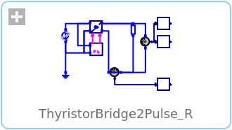
Diagram

Wolfram Language
In[1]:=
SystemModel["Modelica.Electrical.PowerConverters.Examples.ACDC.RectifierBridge2Pulse.ThyristorBridge2Pulse_R"]
Out[1]:=
Information
This information is part of the Modelica Standard Library maintained by the Modelica Association.
This examples shows a two pulse full controlled bridge example with resistive load. In case of resistive load the full controlled bridge shows the same output voltage as the half controlled bridge.
Plot current currentSensor.i, average current meanCurrent.y, voltage voltageSensor.v and average voltage meanVoltage.v.
Parameters (4)
| Vrms |
Value: 110 Type: Voltage (V) Description: RMS supply voltage |
|---|---|
| f |
Value: 50 Type: Frequency (Hz) Description: Frequency |
| constantFiringAngle |
Value: 30 * pi / 180 Type: Angle (rad) Description: Firing angle |
| R |
Value: 20 Type: Resistance (Ω) Description: Load resistance |
Components (10)
| ground |
Type: Ground Description: Ground node |
|
|---|---|---|
| sinevoltage |
Type: SineVoltage Description: Sine voltage source |
|
| rectifier |
Type: ThyristorBridge2Pulse Description: Two pulse Graetz thyristor rectifier bridge |
|
| voltagesensor |
Type: VoltageSensor Description: Sensor to measure the voltage between two pins |
|
| meanVoltage |
Type: Mean Description: Calculate mean over period 1/f |
|
| rootMeanSquareVoltage |
Type: RootMeanSquare Description: Calculate root mean square over period 1/f |
|
| currentSensor |
Type: CurrentSensor Description: Sensor to measure the current in a branch |
|
| meanCurrent |
Type: Mean Description: Calculate mean over period 1/f |
|
| pulse2 |
Type: VoltageBridge2Pulse Description: Control of 2 pulse bridge rectifier |
|
| resistor |
Type: Resistor Description: Ideal linear electrical resistor |