WOLFRAM SYSTEM MODELER
ForceStrokeBehaviourForce-stroke characteristic of the permeance model at constant current |
|
Diagram
Wolfram Language
In[1]:=
SystemModel["Modelica.Magnetic.FluxTubes.Examples.MovingCoilActuator.ForceStrokeBehaviour"]
Out[1]:=
Information
This information is part of the Modelica Standard Library maintained by the Modelica Association.
Have a look at ConstantActuator and at PermeanceActuator for an explanation of both converter models.
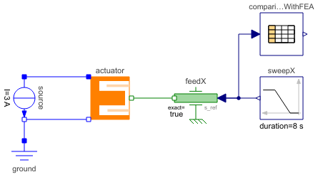
Simulation of the force-stroke characteristic of the PermeanceActuator with a constant current I=3A and a forced armature movement (similar to measurements in reality) shows the dependency of both force-generating permeances G_ma and G_mb as well as inductance L on armature position x. Simulate for 8 s and plot vs. armature position feedX.flange_b.s (same physical quantities together in a common diagram for comparison):
feedX.flange_b.f            // force of permeance model (permeance of stator iron neglected in this model)
comparisonWithFEA.y[1]      // force of FEA model with non-linear stator iron 1.0718
comparisonWithFEA.y[2]      // force of FEA model with mu_rFe=const.=1000
actuator.g_ma.G_m           // permeance G_ma
actuator.g_mb.G_m           // permeance G_mb
actuator.L                  // inductance of permeance model
comparisonWithFEA.y[3]      // inductance of FEA model for comparison (mu_rFe=const.=1000).
Components (6)
| ground |
Type: Ground Description: Ground node |
|
|---|---|---|
| actuator |
Type: PermeanceActuator Description: Detailed actuator model for rough magnetic design of actuator and system simulation |
|
| source |
Type: ConstantCurrent Description: Source for constant current |
|
| sweepX |
Type: Ramp Description: Generate ramp signal |
|
| feedX |
Type: Position Description: Forced movement of a flange according to a reference position |
|
| comparisonWithFEA |
Type: CombiTable1Ds Description: Column 1: position, col.2: force with non-linear stator iron, col.3: force with mu_rFe=const.=1000, col.4: inductance with mu_rFe=const.=1000 |