WOLFRAM SYSTEM MODELER
SinglePhaseInductanceSingle-phase inductance |
|
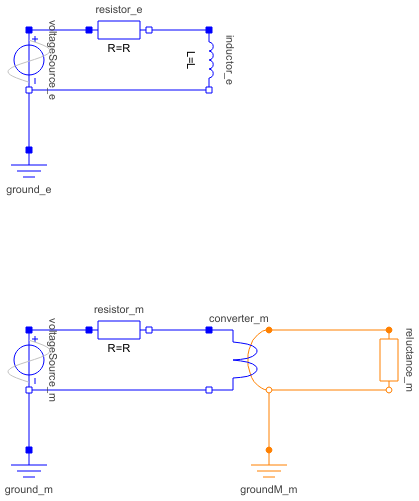
Diagram
Wolfram Language
In[1]:=
SystemModel["Modelica.Magnetic.FundamentalWave.Examples.Components.SinglePhaseInductance"]
Out[1]:=
Information
This information is part of the Modelica Standard Library maintained by the Modelica Association.
This example compares an electric single-phase inductor with an equivalent fundamental wave reluctance circuit.
The phase inductance L and the magnetic fundamental wave reluctance R_m are related by:
R_m = effectiveTurns^2 / L
The two currents
resistor_e.iresistor_m.i
show the same waveforms and thus prove the equivalence of the two different modelling approaches.
Parameters (6)
| f |
Value: 1 Type: Frequency (Hz) Description: Supply frequency |
|---|---|
| VRMS |
Value: 100 Type: Voltage (V) Description: RMS supply voltage |
| R |
Value: 0.1 Type: Resistance (Ω) Description: Leader cable resistance |
| L |
Value: 1 Type: Inductance (H) Description: Load inductance |
| effectiveTurns |
Value: 5 Type: Real Description: Effective number of turns |
| R_m |
Value: effectiveTurns ^ 2 / L Type: Reluctance (H⁻¹) Description: Equivalent magnetic reluctance |
Components (10)
| ground_e |
Type: Ground Description: Ground node |
|
|---|---|---|
| ground_m |
Type: Ground Description: Ground node |
|
| voltageSource_e |
Type: SineVoltage Description: Sine voltage source |
|
| voltageSource_m |
Type: SineVoltage Description: Sine voltage source |
|
| resistor_e |
Type: Resistor Description: Ideal linear electrical resistor |
|
| resistor_m |
Type: Resistor Description: Ideal linear electrical resistor |
|
| inductor_e |
Type: Inductor Description: Ideal linear electrical inductor |
|
| converter_m |
Type: SinglePhaseElectroMagneticConverter Description: Single-phase electromagnetic converter |
|
| reluctance_m |
Type: Reluctance Description: Salient reluctance |
|
| groundM_m |
Type: Ground Description: Magnetic ground |