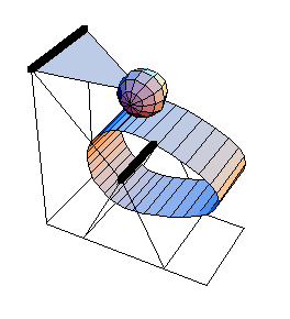
6.1.4 Example 3D Cam MechanismTo demonstrate the use of Modeler3D cam functions, a 3D model of a rotating cam with a spherical follower is developed. The model consists of two moving bodies, the cam and the follower. Here is the 3D cam-follower model.

Cam ProfileThe cam profile used for this mechanism is defined in terms of trigonometric functions of the symbols alpha and beta. The cam profile expression may contain user-defined parameters that are defined at runtime, but all of the functional dependence on the controlling parameters, alpha and beta, must be present when the cam profile is processed with SetConstraints. Thus, it is not possible to leave the cam profile defined as simply a three element list of symbols, such as {xcam, ycam, zcam}, and then define xcam, ycam, and zcam as functions of alpha and beta at runtime.
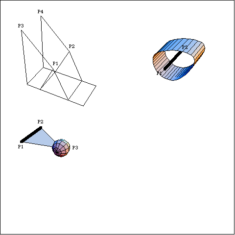
The cam surface is the same as the one developed and plotted in Section 6.1.3. Here are the parametric expressions defining the locus of the cam surface. BodiesThree bodies are used for the cam-follower model. Names are defined for each of the body numbers in the model. Four points are required on the ground (body 1).
P1 and P2 are the two ends of the rotational axis of the cam at local coordinates {0, 0, 0} and {0, 2, 0}.
P3 and P4 are the two ends of the rotational axis of the follower at local coordinates {- 2, 0, 2} and {- 2, 2, 2}.Three points are required on the cam (body 2).
P1 and P2 are the two ends of the rotational axis of the cam at local coordinates {0, 0, 0} and {0, 2, 0}.
P3 is the locus point of the cam that was previously defined and named camsurf.Three points are required on the follower (body 3).
P1 and P2 are the two ends of the rotational axis of the follower at local coordinates {0, 0, 0} and {0, 2, 0}.
P3 is the center of the spherical cam follower at {2, 1, 0}.Here are all of the bodies in the cam model.

SetBodies is used here only to set a nonzero initial guess for the follower. ConstraintsThree regular constraints and one cam constraint are required to model the cam-follower mechanism. A Revolute5 constraint forces the axis of the cam to be coincident with its rotational axis on the ground.A Revolute5 constraint forces the pivot axis of the follower to be coincident with its axis on the ground.A ProjectedAngle1 constraint controls the angular coordinate of the cam. This driving constraint specifies the rotation of the cam as a function of T.A CamToSphere1 constraint controls the one remaining degree of freedom. The point arguments to CamToSphere1 are given in the same syntax as would be used with any other Modeler3D constraint, except for the requirement that the local coordinates of the locuspoint be a function of the symbols, alpha and beta.Note that while CamToSphere1 constrains one degree of freedom in the model, it actually adds three equations (one that forces the spherical follower to lie a specified distance away from the cam surface, and two more that force the cam surface to be tangent at the point of contact) and two unknowns, alpha and beta, to the model. Here are the constraints for the cam-follower mechanism. RuntimeThe cam-follower mechanism model can now be run in the usual manner. Note the presence of the cam parameters, alpha and beta, in the solution rule. At these values of alpha and beta the cam locus point is placed at the point of contact between the cam and the follower. Now the model is run at T = 0.10.
Out[31]= |  |
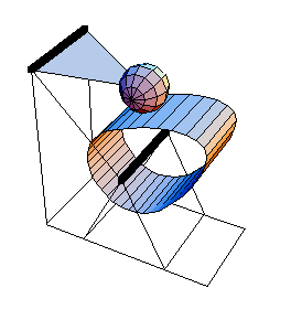
Here is the cam-follower mechanism at T = 0.1.

The model is run again at T = 0.20.
Out[32]= |  |
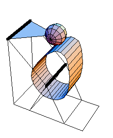
Here is the cam-follower at T = 0.20.

|