6.1.5 Splined CamsIn designing an arbitrary cam mechanism it is necessary to be able to describe an arbitrary cam surface, one that is not constrained to be a series of piecewise continuous functions each coded in by the user, such as the examples in Sections 6.1.2 and 6.1.4. One way to define such an arbitrary curve or surface is with Mathematica's InterpolatingFunction objects built with the Interpolation function. Thus, the required sequence of piecewise continuous functions is assembled by Mathematica, while the user merely inputs discrete data.
While a cam surface so defined may work in a Mech model, it may also create some numerical problems. One basic requirement for a valid Mech cam profile is that it have zeroth- and first-order continuity. The Interpolation function uses cubic interpolation to fit the polynomials to the supplied data. This results in a curve that has zeroth-order, not first-order, continuity. Since the first-order discontinuities in an InterpolatingFunction cam are typically small, such a cam usually works fine until it happens to seek a solution point that has its point of contact on the cam directly on a cusp in the interpolating function.
To get around this difficulty Mech provides a function for creating cubic spline objects that have zeroth-, first-, and second-order continuity at each knot point. Mech's SplineFit function is similar to the SplineFit function that is included with the standard Mathematica packages, but it has been enhanced to allow 3D space curves, and the SplineFunction objects it returns are differentiable.

The function for creating splines. Options for SplineFit. Note that it is necessary to provide a list of data points with identical first and last points if a Closed spline is desired. The EndConditions -> Closed setting only ensures that the slope and curvature are continuous at the ends. The supplied data must provide zeroth-order continuity.
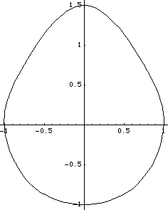
A closed cam profile in 2D space could be defined with a SplineFunction object. This loads the Modeler2D package. Here is some data to be splined. Now we generate a SplineFunction object.
Out[35]= |  |
Here is a plot of the spline.

Out[36]= |  |
If it were desired to use this cam profile in a Modeler2D model with a circular cam follower, the following constraint syntax could be used. This constraint implies that the cam is on body 2, the circular follower is on the origin of body 3 and has a radius of 0.2, the constraint is constraint 4, and the initial guess for the cam parameter s is 2.0. Here is a cam constraint that uses a splined cam.
Out[37]= |  |
|