11.1 Generalized Coordinate ConstraintsThe generalized coordinate constraints are not, in fact, constraints at all. Each generalized coordinate constraint is named like a standard constraint, takes approximately the same arguments as a standard constraint, returns a SysCon constraint object that is passed to SetConstraints, and generally appears in a mechanism model in exactly the same way as the standard Modeler2D and Modeler3D constraints. The difference between them is best illustrated by an example.
Consider a standard Modeler2D model containing a Translate2 constraint that models a translational joint between body 2 and the ground. The presence of the constraint object causes SetConstraints to do two things: three degrees of freedom (the symbols X2, Y2, and  2) are added to the model to represent body 2, and two degrees of freedom are removed from the model by the two constraint equations in the constraint. The net effect, then, is to add one degree of freedom to the model that must be constrained by some other constraint. If the Translate2 constraint is replaced with a GenTranslate2 constraint, SetConstraints does only one thing: one degree of freedom is added to the model by adding a single symbol to the dependent variable list. The name of the symbol is specified in the GenTranslate2 constraint object. 2) are added to the model to represent body 2, and two degrees of freedom are removed from the model by the two constraint equations in the constraint. The net effect, then, is to add one degree of freedom to the model that must be constrained by some other constraint. If the Translate2 constraint is replaced with a GenTranslate2 constraint, SetConstraints does only one thing: one degree of freedom is added to the model by adding a single symbol to the dependent variable list. The name of the symbol is specified in the GenTranslate2 constraint object.
Body 2, which was represented by three symbols, is now represented by only one. All of Mech's other constraint, load, output, and graphics functions can recognize and access body 2 just as if it were a standard body; the only difference is that the symbolic representation of all geometry on the body is a function of just one symbol, not three.
Note that generalized coordinate constraints cannot be used within the multistage constraint objects, TimeSwitch or StageSwitch. This is simply because including them in a multistage constraint would have no effect on the model; the generalized coordinate constraints contain no constraint equations, so there is nothing to switch on and off. 11.1.1 2D ConstraintsThere are only two 2D generalized coordinate constraints. The wide variety of standard 2D constraints cannot be meaningfully converted to generalized constraints; only constraints which attach exactly two bodies together such that only one degree of freedom remains between them are generally useful.
The arguments given to the generalized coordinate constraints are of the same form as the arguments given to the standard constraints. However, each of these constraints requires an additional argument to specify the name of, and an initial guess for, the new symbol that represents the added degree of freedom. The 2D generalized coordinate constraints. Note that there is a clear distinction between a master and slave bodies. The slave body is the one that will be represented by the single new generalized coordinate. Thus, the slave body cannot be the ground body. The master body may be the ground body, another body represented by standard coordinates, or another body represented by generalized coordinates that was created with another generalized constraint. The master-slave relationship cannot be circular; the master-slave chain must originate from the ground, or from a standard body. Also, a slave body cannot be a slave to more than one master body.
Another restriction on the arguments to generalized coordinate constraints is that the axis objects, axis1 and axis2, must each be defined entirely on a single body. While standard constraints allow axis objects to span multiple bodies (such as a line originating on one body and ending on another) generalized coordinate constraints do not. ExampleThe following example shows a standard constraint and a generalized coordinate constraint that could be used to perform exactly the same function in a model. Here are two functionally equivalent constraints.
Out[4]= |  |
Out[5]= |  |
11.1.2 3D ConstraintsThere are only four 3D generalized coordinate constraints. The wide variety of standard 3D constraints cannot be meaningfully converted to generalized constraints; only constraints that attach exactly two bodies together such that only one or two degrees of freedom remain between them are generally useful.
The arguments given to the generalized coordinate constraints are of the same form as the arguments given to the standard constraints. However, each of these constraints requires additional arguments to specify the names of, and an initial guesses for, the new symbol or symbols that represent the added degrees of freedom. The 3D generalized coordinate constraints. Note that there is a clear distinction between a master and slave bodies. The slave body is the one that will be represented by the single new generalized coordinate. Thus, the slave body cannot be the ground body. The master body may be the ground body, another body represented by standard coordinates, or another body represented by generalized coordinates that was created with another generalized constraint. The master-slave relationship cannot be circular; the master-slave chain must eventually lead back to the ground, or to a standard body.
Another restriction on the arguments to generalized coordinate constraints is that the axis objects, axis1 and axis2, must each be defined entirely on a single body. While standard constraints allow axis objects to span multiple bodies (such as a line originating on one body and ending on another) generalized coordinate constraints do not. ExampleThe following example shows a standard constraint and a generalized coordinate constraint that could be used to perform exactly the same function in a model. Here are two functionally equivalent constraints.
Out[9]= |  |
Out[10]= |  |
11.1.3 User-Defined Generalized ConstraintIf the selection of predefined generalized coordinate constraints is not sufficient, the GenConstraint function can be used to create constraints with any number of generalized coordinates representing any geometric relationship between two bodies that can be written algebraically. The user-defined generalized coordinate constraint. In Modeler2D, rotation is a counterclockwise angle. In Modeler3D, rotation is specified in the {ang, axis} format, and it can be a single rotation or a sequence of rotations of the form used by RotationLock3.
The trick to creating a valid constraint with GenConstraint is to make the pointi and rotation arguments symbolic functions of the generalized coordinate symbols symi. For example, the following constraint object would introduce a slave body that is constrained so that its origin lies on a parabola in the Y-Z plane, and its rotation is about the Z axis only. The position of the body along the parabola is represented by tau, and the rotation angle of the body about the Z axis is represented by phi. Here is a GenConstraint example.
Out[11]= |  |
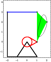
11.1.4 Four-Bar Example MechanismTo demonstrate the use of generalized coordinate constraints in a Modeler2D model, a 2D model of a simple four-bar mechanism is developed. The model consists of three moving bars and one stationary bar, the ground. This same model is also used in Section 8.3 and Chapter 9, so it is presented very briefly here. This loads the Modeler2D packages. Here is the four-bar mechanism, shown with the locus of a moving point.
Bodies Four body objects are required for the four-bar model. Each bar is attached to another bar at its local origin and at a point at the other end of the bar on the local X or Y axis. The ground (body 1) uses two points.
P0 is the attachment point of the drive bar.
P1 is the attachment point of the driven bar.The drive bar (body2) uses two points.
P0 is the rotational axis of the drive bar.
P1 is the attachment point of the center bar.The driven bar (body3) uses two points.
P0 is the rotational axis of the driven bar.
P1 is the attachment point of the center bar.The center bar (body 4) uses three points.
P0 is the attachment point of the drive bar.
P1 is the attachment point of the driven bar.
P2 is an offset point used for tracking a point locus.Here are the body objects for the four-bar model. The body properties are incorporated into the model. ConstraintsFive constraints, one of which is a driving constraint, are used to model the four-bar mechanism. These constraints are simply standard Mech constraints that will be replaced with generalized coordinate constraints shortly. A RotationLock1 constraint is used as a driving constraint to rotate the drive bar.Four Revolute2 constraints model the four pivot points in the four-bar mechanism.Here are the constraint objects for the four-bar. The constraints are incorporated into the current model. RuntimeBecause of the presence of T in the driving constraint cs[1], the model can be run through its intended range of motion by varying T directly with the SolveMech command. The numerical value of T specifies the angle of rotation of the drive bar in revolutions. The model is run at T = 0.3.
Out[27]= |  |
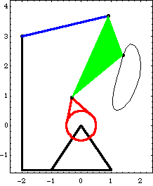
Here is the four-bar model at T = 0.3.
Generalized Coordinate ConstraintsNow one of the standard constraints is replaced with a generalized coordinate constraint. Constraint 2, the revolute joint at the drive bar origin, is replaced first, and body 2 becomes a slave to the ground body, represented by the single coordinate alpha. Here is the new constraint. The modified model is run again at T = 0.3.
Out[30]= |  |
Note that the symbols X2, Y2, and  2 are no longer included in the solution rules returned by SolveMech. The location of body 2 is represented entirely by alpha, which has the same numerical value as 2 are no longer included in the solution rules returned by SolveMech. The location of body 2 is represented entirely by alpha, which has the same numerical value as  2 used to have. The numerical value of alpha would be different from 2 used to have. The numerical value of alpha would be different from  2 if the direction vectors of the two axes in the GenRevolute2 constraint were not identical (X and X). 2 if the direction vectors of the two axes in the GenRevolute2 constraint were not identical (X and X).
Two more of the Revolute2 constraints can also be replaced, but not the fourth one. This is because each generalized coordinate constraint creates a slave body, and a slave body can be a slave to only one master body. Thus, there is no way to use four generalized coordinate constraints in a model with only three bodies. Any three of the four revolute constraints can be replaced, but not all of them. Here are two more new constraints. The modified model is run again at T = 0.3.
Out[34]= |  |
Now all of the Cartesian coordinates have been replaced with the generalized coordinates alpha, beta, and gamma. A quick degree of freedom count shows that this all makes sense: the three generalized coordinate constraints each add one degree of freedom to the model, while the two standard constraints Revolute2 and RotationLock1 constrain a total of three degrees of freedom.
The physical meaning of the new coordinates is quite clear: alpha is the angle between the X axis of the ground and the local x axis of the drive bar, beta is the angle between the local x axes of the drive and center bars, and gamma is the angle between the local x axes of the center and driven bars. Output and Graphics FunctionsNow that we have a solution in terms of the generalized coordinates, all of the standard Mech output and graphics functions allow it to be used in the same manner as a solution in Cartesian coordinates. For example, the location of a point is still found with the Location function and the rotation angle of a body is found with Rotation. The symbolic expressions returned by these functions reflect the new coordinate system being used, but the numerical results are equivalent. Here are the Cartesian coordinates of point 2 on the center bar.
Out[35]= |  |
Out[36]= |  |
Here is the global rotation angle of the driven bar. Note that it is numerically equal to the  3 coordinate from the first set of solution rules. 3 coordinate from the first set of solution rules.
Out[37]= |  |
Out[38]= |  |
The location of point 2 on the center bar is a function of alpha and beta, but not gamma. This is because of the master-slave relationship of the generalized coordinate bodies; the center bar is a slave to the drive bar, which is a slave to the ground. Thus, the location of any point on the driven bar is a function of all three generalized coordinates, and the location of any point on the drive bar is a function of only alpha.
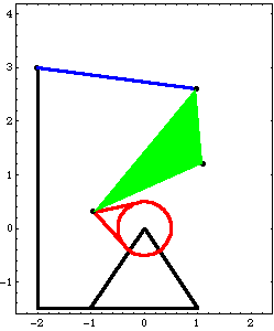
Mech graphics functions also operate without regard to the use of generalized coordinates. The following graphics object will generate the same image with any of the three constraint formulations used previously. Here is the graphics object representing the four-bar model. This shows the graphic at T = 0.45.
Out[40]= |  |
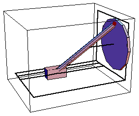
11.1.5 Space-Crank Example MechanismTo demonstrate the use of generalized coordinate constraints in a Modeler3D model, a 3D model of a spatial slider-crank mechanism is developed. The model consists of three moving bodies; a slider, crank, and connecting rod. A geometrically similar model is presented in Section 3.2. The model presented here differs in that it uses a separate body to represent the connecting rod, instead of simply replacing it with a relative-distance constraint. This loads the Modeler3D packages. Here is the complete space-crank graphic.
Bodies Four body objects are defined for the space-crank model. Note the use of the zeroth point to avoid having to define {0, 0, 0}. The ground (body 1) has one point defined in its body object.
P1 is a point to locate the rotational axis of the crank.The crank (body 2) has one point defined in its body object.
P1 is the attachment point of the connecting rod. The center of the crank is at the local origin.The connecting rod (body 3) has one point defined in its body object.
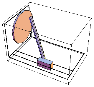
P1 is the attachment point of the connecting rod to the slider, while the connecting rod is attached to the crank at P0.The slider (body 4) has no points in its body object, only an initial guess, because only the local origin P0 is used.Here are the body objects for the space-crank model. The body properties are incorporated into the model. ConstraintsFive constraints, one of which is a driving constraint, are used to model the space-crank mechanism. These constraints are simply standard Mech constraints that will be replaced with generalized coordinate constraints shortly. A ProjectedAngle1 constraint specifies the angular relationship between a line on the ground body and a line on the crank. This driving constraint is used to rotate the crank.A Revolute5 constraint forces the axis of the crank to be coincident with its pivot axis on the ground.A Spherical3 constraint between the crank and the connecting rod models a ball joint.An OrthoRevolute4 constraint between the slider and the connecting rod models a universal joint. This is used instead of a Spherical3 constraint so as to constrain the spin of the connecting rod about its own longitudinal axis.A Translate5 constraint between the slider and the ground allows translation of the slider.Here are the constraint objects for the space-crank mechanism. The constraints are incorporated into the model. RuntimeThe model can now be run through its range of motion by varying T with the SolveMech command. The numerical value of T specifies the angle of rotation of the crank in revolutions. The model is run at T = 0.05.
Out[57]= |  |
Here is the slider-crank model at T = 0.05.
Generalized Coordinate ConstraintsNow one of the standard constraints is replaced with a generalized coordinate constraint. Constraint 2, the revolute joint that models the rotational axis of the crank, is replaced first, and body 2 becomes a slave to the ground body, represented by the single coordinate alpha. Note that the arguments to the GenRevolute5 constraint are exactly the same as the arguments to the Revolute5 constraint, with the addition of the new symbol alpha and its initial guess. Here is the new constraint. The modified model is run again at T = 0.05.
Out[60]= |  |
Note that all of the symbols associated with body 2 are no longer included in the solution rules returned by SolveMech. The location of body 2 is represented entirely by alpha, which is the rotation angle of the crank in full revolutions. The definition (and hence the numerical value) of alpha is dependent on the relative reference directions of the two axis objects passed to GenRevolute5. Since the reference directions were not explicitly specified in the axis objects, default reference directions were assumed by Mech (the local y axes of each body, in this case).
Only two more of the standard Mech constraints in this model can be replaced with generalized coordinate constraints. This is because each generalized coordinate constraint creates a slave body, and a slave body can be a slave to only one master body. Thus, there is no way to use more than three generalized coordinate constraints in a model with only three bodies. Here are two more new constraints. The modified model is run again at T = 0.05.
Out[64]= |  |
Now the 21 Cartesian and Euler coordinates have been replaced with the four generalized coordinates alpha, beta, gamma, and delta. A quick degree of freedom count shows that this all makes sense: the three generalized coordinate constraints add a total of four degrees of freedom to the model, while the two remaining standard constraints Spherical3 and ProjectedAngle1 constrain a total of four degrees of freedom.
The physical meaning of the new coordinates is somewhat confusing: alpha is simply the angle between the global Y axis and the local y axis of the crank, and delta is the X direction distance from the global origin to the origin of the slider. beta and gamma are two angles that represent the rotation of the connecting rod with respect to the slider: beta is the altitude angle, the angle between a horizontal plane and a vector down the axis of the connecting rod, and gamma is the azimuth angle, the rotation of the connecting rod axis about the global Z axis.
Finally, to reduce the mathematical model of the space-crank mechanism to the absolute minimum size, constraint 1 (the ProjectedAngle1 constraint) must be reexamined. This constraint uses a rather complicated expression relating the directions of three vectors to specify the rotation of the crank, but it is known that the rotation of the crank can be directly specified by alpha. While Mech attempts to simplify constraint expressions to some extent, the algebraic expression generated by constraint 1 is more complicated than it could be. Here is the expression that results from constraint 1.
Out[65]= |  |
Constraint 1 really just sets alpha equal to 2 Pi T, which can be done more directly with the all-purpose constraint function Constraint. Here is a simplified functional replacement for constraint 1.
Out[66]= |  |
Output and Graphics FunctionsNow that we have a solution in terms of generalized coordinates, all of the standard Mech output and graphics functions allow it to be used in the same manner as a solution in terms of Cartesian and Euler coordinates. For example, the location of a point is still found with the Location function and the spatial orientation of a body is found with Rotation. The symbolic expressions returned by these functions reflect the new coordinate system being used, but the numerical results are equivalent. Here are the Cartesian coordinates of a point at the center of the connecting rod.
Out[67]= |  |
Out[68]= |  |
The location of the point on the connecting rod is a function of beta, gamma, and delta, but not alpha. This is because of the master-slave relationship of the generalized coordinate bodies; the connecting rod is a slave to the slider, which is a slave to the ground. Thus, the location of any point on the connecting rod is a function of the generalized coordinates of the slider and the connecting rod, while the location of any point on the crank is a function of only alpha. Here is the global rotation angle of the crank.
Out[69]= |  |
Out[70]= |  |
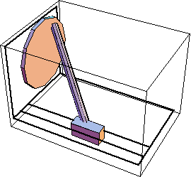
Mech graphics functions also operate without regard to the use of generalized coordinates. The following graphics object will generate the same image with any of the three constraint formulations used in the preceding example. Here is the graphics object representing the space-crank model. This shows the graphic at T = 0.15.
Out[72]= |  |
|