|
11. Generalized Coordinates OverviewThis chapter covers the use of user-defined generalized coordinates to represent the location of some or all of the bodies in a MechanicalSystems model, replacing the reference point coordinates that are used by default. The primary utility of this technique is to increase the performance of multibody models by reducing the total number of symbolic coordinates used.
Standard Mech models are made up of one or more independent bodies, each of which is represented by three, four, or seven Cartesian and Euler coordinates. While this representation is very general, and allows bodies to be interconnected in an unrestricted manner, it inevitably causes many more symbolic coordinates to be included in the model than are required to represent its motion.
For example, a 3D body that is attached to the ground with a revolute joint (a Revolute5 constraint in MechanicalSystems) would normally be represented by seven coordinates. While all these coordinates are necessary to completely define the location and orientation of the body, we are really concerned with only one of them; the single coordinate representing rotation about the revolute axis. The other coordinates may be just excess baggage, conveying trivial, constant information that we do not need. Using generalized coordinates allows such a body to be represented by a single coordinate, supplied by the user.
Note that there are pros and cons to using generalized coordinates. Some information, such as constraint reaction forces, are lost when a constraint is eliminated from the model with generalized coordinates. This notebook contains general guidelines to help determine when to use generalized coordinates, and when to use Mech's standard representation. 11.1 Generalized Coordinate ConstraintsThe generalized coordinate constraints are not, in fact, constraints at all. Each generalized coordinate constraint is named like a standard constraint, takes approximately the same arguments as a standard constraint, returns a SysCon constraint object that is passed to SetConstraints, and generally appears in a mechanism model in exactly the same way as the standard Modeler2D and Modeler3D constraints. The difference between them is best illustrated by an example.
Consider a standard Modeler2D model containing a Translate2 constraint that models a translational joint between body 2 and the ground. The presence of the constraint object causes SetConstraints to do two things: three degrees of freedom (the symbols X2, Y2, and  2) are added to the model to represent body 2, and two degrees of freedom are removed from the model by the two constraint equations in the constraint. The net effect, then, is to add one degree of freedom to the model that must be constrained by some other constraint. If the Translate2 constraint is replaced with a GenTranslate2 constraint, SetConstraints does only one thing: one degree of freedom is added to the model by adding a single symbol to the dependent variable list. The name of the symbol is specified in the GenTranslate2 constraint object. 2) are added to the model to represent body 2, and two degrees of freedom are removed from the model by the two constraint equations in the constraint. The net effect, then, is to add one degree of freedom to the model that must be constrained by some other constraint. If the Translate2 constraint is replaced with a GenTranslate2 constraint, SetConstraints does only one thing: one degree of freedom is added to the model by adding a single symbol to the dependent variable list. The name of the symbol is specified in the GenTranslate2 constraint object.
Body 2, which was represented by three symbols, is now represented by only one. All of Mech's other constraint, load, output, and graphics functions can recognize and access body 2 just as if it were a standard body; the only difference is that the symbolic representation of all geometry on the body is a function of just one symbol, not three.
Note that generalized coordinate constraints cannot be used within the multistage constraint objects, TimeSwitch or StageSwitch. This is simply because including them in a multistage constraint would have no effect on the model; the generalized coordinate constraints contain no constraint equations, so there is nothing to switch on and off. 11.1.1 2D ConstraintsThere are only two 2D generalized coordinate constraints. The wide variety of standard 2D constraints cannot be meaningfully converted to generalized constraints; only constraints which attach exactly two bodies together such that only one degree of freedom remains between them are generally useful.
The arguments given to the generalized coordinate constraints are of the same form as the arguments given to the standard constraints. However, each of these constraints requires an additional argument to specify the name of, and an initial guess for, the new symbol that represents the added degree of freedom. The 2D generalized coordinate constraints. Note that there is a clear distinction between a master and slave bodies. The slave body is the one that will be represented by the single new generalized coordinate. Thus, the slave body cannot be the ground body. The master body may be the ground body, another body represented by standard coordinates, or another body represented by generalized coordinates that was created with another generalized constraint. The master-slave relationship cannot be circular; the master-slave chain must originate from the ground, or from a standard body. Also, a slave body cannot be a slave to more than one master body.
Another restriction on the arguments to generalized coordinate constraints is that the axis objects, axis1 and axis2, must each be defined entirely on a single body. While standard constraints allow axis objects to span multiple bodies (such as a line originating on one body and ending on another) generalized coordinate constraints do not. ExampleThe following example shows a standard constraint and a generalized coordinate constraint that could be used to perform exactly the same function in a model. Here are two functionally equivalent constraints.
Out[4]= |  |
Out[5]= |  |
11.1.2 3D ConstraintsThere are only four 3D generalized coordinate constraints. The wide variety of standard 3D constraints cannot be meaningfully converted to generalized constraints; only constraints that attach exactly two bodies together such that only one or two degrees of freedom remain between them are generally useful.
The arguments given to the generalized coordinate constraints are of the same form as the arguments given to the standard constraints. However, each of these constraints requires additional arguments to specify the names of, and an initial guesses for, the new symbol or symbols that represent the added degrees of freedom. The 3D generalized coordinate constraints. Note that there is a clear distinction between a master and slave bodies. The slave body is the one that will be represented by the single new generalized coordinate. Thus, the slave body cannot be the ground body. The master body may be the ground body, another body represented by standard coordinates, or another body represented by generalized coordinates that was created with another generalized constraint. The master-slave relationship cannot be circular; the master-slave chain must eventually lead back to the ground, or to a standard body.
Another restriction on the arguments to generalized coordinate constraints is that the axis objects, axis1 and axis2, must each be defined entirely on a single body. While standard constraints allow axis objects to span multiple bodies (such as a line originating on one body and ending on another) generalized coordinate constraints do not. ExampleThe following example shows a standard constraint and a generalized coordinate constraint that could be used to perform exactly the same function in a model. Here are two functionally equivalent constraints.
Out[9]= |  |
Out[10]= |  |
11.1.3 User-Defined Generalized ConstraintIf the selection of predefined generalized coordinate constraints is not sufficient, the GenConstraint function can be used to create constraints with any number of generalized coordinates representing any geometric relationship between two bodies that can be written algebraically. The user-defined generalized coordinate constraint. In Modeler2D, rotation is a counterclockwise angle. In Modeler3D, rotation is specified in the {ang, axis} format, and it can be a single rotation or a sequence of rotations of the form used by RotationLock3.
The trick to creating a valid constraint with GenConstraint is to make the pointi and rotation arguments symbolic functions of the generalized coordinate symbols symi. For example, the following constraint object would introduce a slave body that is constrained so that its origin lies on a parabola in the Y-Z plane, and its rotation is about the Z axis only. The position of the body along the parabola is represented by tau, and the rotation angle of the body about the Z axis is represented by phi. Here is a GenConstraint example.
Out[11]= |  |
11.1.4 Four-Bar Example MechanismTo demonstrate the use of generalized coordinate constraints in a Modeler2D model, a 2D model of a simple four-bar mechanism is developed. The model consists of three moving bars and one stationary bar, the ground. This same model is also used in Section 8.3 and Chapter 9, so it is presented very briefly here. This loads the Modeler2D packages. Here is the four-bar mechanism, shown with the locus of a moving point.
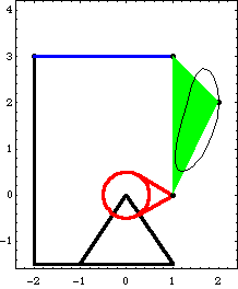
Bodies Four body objects are required for the four-bar model. Each bar is attached to another bar at its local origin and at a point at the other end of the bar on the local X or Y axis. The ground (body 1) uses two points.
P0 is the attachment point of the drive bar.
P1 is the attachment point of the driven bar.The drive bar (body2) uses two points.
P0 is the rotational axis of the drive bar.
P1 is the attachment point of the center bar.The driven bar (body3) uses two points.
P0 is the rotational axis of the driven bar.
P1 is the attachment point of the center bar.The center bar (body 4) uses three points.
P0 is the attachment point of the drive bar.
P1 is the attachment point of the driven bar.
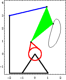
P2 is an offset point used for tracking a point locus.Here are the body objects for the four-bar model. The body properties are incorporated into the model. ConstraintsFive constraints, one of which is a driving constraint, are used to model the four-bar mechanism. These constraints are simply standard Mech constraints that will be replaced with generalized coordinate constraints shortly. A RotationLock1 constraint is used as a driving constraint to rotate the drive bar.Four Revolute2 constraints model the four pivot points in the four-bar mechanism.Here are the constraint objects for the four-bar. The constraints are incorporated into the current model. RuntimeBecause of the presence of T in the driving constraint cs[1], the model can be run through its intended range of motion by varying T directly with the SolveMech command. The numerical value of T specifies the angle of rotation of the drive bar in revolutions. The model is run at T = 0.3.
Out[27]= |  |
Here is the four-bar model at T = 0.3.
Generalized Coordinate ConstraintsNow one of the standard constraints is replaced with a generalized coordinate constraint. Constraint 2, the revolute joint at the drive bar origin, is replaced first, and body 2 becomes a slave to the ground body, represented by the single coordinate alpha. Here is the new constraint. The modified model is run again at T = 0.3.
Out[30]= |  |
Note that the symbols X2, Y2, and  2 are no longer included in the solution rules returned by SolveMech. The location of body 2 is represented entirely by alpha, which has the same numerical value as 2 are no longer included in the solution rules returned by SolveMech. The location of body 2 is represented entirely by alpha, which has the same numerical value as  2 used to have. The numerical value of alpha would be different from 2 used to have. The numerical value of alpha would be different from  2 if the direction vectors of the two axes in the GenRevolute2 constraint were not identical (X and X). 2 if the direction vectors of the two axes in the GenRevolute2 constraint were not identical (X and X).
Two more of the Revolute2 constraints can also be replaced, but not the fourth one. This is because each generalized coordinate constraint creates a slave body, and a slave body can be a slave to only one master body. Thus, there is no way to use four generalized coordinate constraints in a model with only three bodies. Any three of the four revolute constraints can be replaced, but not all of them. Here are two more new constraints. The modified model is run again at T = 0.3.
Out[34]= |  |
Now all of the Cartesian coordinates have been replaced with the generalized coordinates alpha, beta, and gamma. A quick degree of freedom count shows that this all makes sense: the three generalized coordinate constraints each add one degree of freedom to the model, while the two standard constraints Revolute2 and RotationLock1 constrain a total of three degrees of freedom.
The physical meaning of the new coordinates is quite clear: alpha is the angle between the X axis of the ground and the local x axis of the drive bar, beta is the angle between the local x axes of the drive and center bars, and gamma is the angle between the local x axes of the center and driven bars. Output and Graphics FunctionsNow that we have a solution in terms of the generalized coordinates, all of the standard Mech output and graphics functions allow it to be used in the same manner as a solution in Cartesian coordinates. For example, the location of a point is still found with the Location function and the rotation angle of a body is found with Rotation. The symbolic expressions returned by these functions reflect the new coordinate system being used, but the numerical results are equivalent. Here are the Cartesian coordinates of point 2 on the center bar.
Out[35]= |  |
Out[36]= |  |
Here is the global rotation angle of the driven bar. Note that it is numerically equal to the  3 coordinate from the first set of solution rules. 3 coordinate from the first set of solution rules.
Out[37]= |  |
Out[38]= |  |
The location of point 2 on the center bar is a function of alpha and beta, but not gamma. This is because of the master-slave relationship of the generalized coordinate bodies; the center bar is a slave to the drive bar, which is a slave to the ground. Thus, the location of any point on the driven bar is a function of all three generalized coordinates, and the location of any point on the drive bar is a function of only alpha.
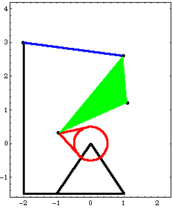
Mech graphics functions also operate without regard to the use of generalized coordinates. The following graphics object will generate the same image with any of the three constraint formulations used previously. Here is the graphics object representing the four-bar model. This shows the graphic at T = 0.45.
Out[40]= |  |
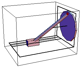
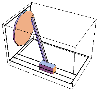
11.1.5 Space-Crank Example MechanismTo demonstrate the use of generalized coordinate constraints in a Modeler3D model, a 3D model of a spatial slider-crank mechanism is developed. The model consists of three moving bodies; a slider, crank, and connecting rod. A geometrically similar model is presented in Section 3.2. The model presented here differs in that it uses a separate body to represent the connecting rod, instead of simply replacing it with a relative-distance constraint. This loads the Modeler3D packages. Here is the complete space-crank graphic.
Bodies Four body objects are defined for the space-crank model. Note the use of the zeroth point to avoid having to define {0, 0, 0}. The ground (body 1) has one point defined in its body object.
P1 is a point to locate the rotational axis of the crank.The crank (body 2) has one point defined in its body object.
P1 is the attachment point of the connecting rod. The center of the crank is at the local origin.The connecting rod (body 3) has one point defined in its body object.
P1 is the attachment point of the connecting rod to the slider, while the connecting rod is attached to the crank at P0.The slider (body 4) has no points in its body object, only an initial guess, because only the local origin P0 is used.Here are the body objects for the space-crank model. The body properties are incorporated into the model. ConstraintsFive constraints, one of which is a driving constraint, are used to model the space-crank mechanism. These constraints are simply standard Mech constraints that will be replaced with generalized coordinate constraints shortly. A ProjectedAngle1 constraint specifies the angular relationship between a line on the ground body and a line on the crank. This driving constraint is used to rotate the crank.A Revolute5 constraint forces the axis of the crank to be coincident with its pivot axis on the ground.A Spherical3 constraint between the crank and the connecting rod models a ball joint.An OrthoRevolute4 constraint between the slider and the connecting rod models a universal joint. This is used instead of a Spherical3 constraint so as to constrain the spin of the connecting rod about its own longitudinal axis.A Translate5 constraint between the slider and the ground allows translation of the slider.Here are the constraint objects for the space-crank mechanism. The constraints are incorporated into the model. RuntimeThe model can now be run through its range of motion by varying T with the SolveMech command. The numerical value of T specifies the angle of rotation of the crank in revolutions. The model is run at T = 0.05.
Out[57]= |  |
Here is the slider-crank model at T = 0.05.
Generalized Coordinate ConstraintsNow one of the standard constraints is replaced with a generalized coordinate constraint. Constraint 2, the revolute joint that models the rotational axis of the crank, is replaced first, and body 2 becomes a slave to the ground body, represented by the single coordinate alpha. Note that the arguments to the GenRevolute5 constraint are exactly the same as the arguments to the Revolute5 constraint, with the addition of the new symbol alpha and its initial guess. Here is the new constraint. The modified model is run again at T = 0.05.
Out[60]= |  |
Note that all of the symbols associated with body 2 are no longer included in the solution rules returned by SolveMech. The location of body 2 is represented entirely by alpha, which is the rotation angle of the crank in full revolutions. The definition (and hence the numerical value) of alpha is dependent on the relative reference directions of the two axis objects passed to GenRevolute5. Since the reference directions were not explicitly specified in the axis objects, default reference directions were assumed by Mech (the local y axes of each body, in this case).
Only two more of the standard Mech constraints in this model can be replaced with generalized coordinate constraints. This is because each generalized coordinate constraint creates a slave body, and a slave body can be a slave to only one master body. Thus, there is no way to use more than three generalized coordinate constraints in a model with only three bodies. Here are two more new constraints. The modified model is run again at T = 0.05.
Out[64]= |  |
Now the 21 Cartesian and Euler coordinates have been replaced with the four generalized coordinates alpha, beta, gamma, and delta. A quick degree of freedom count shows that this all makes sense: the three generalized coordinate constraints add a total of four degrees of freedom to the model, while the two remaining standard constraints Spherical3 and ProjectedAngle1 constrain a total of four degrees of freedom.
The physical meaning of the new coordinates is somewhat confusing: alpha is simply the angle between the global Y axis and the local y axis of the crank, and delta is the X direction distance from the global origin to the origin of the slider. beta and gamma are two angles that represent the rotation of the connecting rod with respect to the slider: beta is the altitude angle, the angle between a horizontal plane and a vector down the axis of the connecting rod, and gamma is the azimuth angle, the rotation of the connecting rod axis about the global Z axis.
Finally, to reduce the mathematical model of the space-crank mechanism to the absolute minimum size, constraint 1 (the ProjectedAngle1 constraint) must be reexamined. This constraint uses a rather complicated expression relating the directions of three vectors to specify the rotation of the crank, but it is known that the rotation of the crank can be directly specified by alpha. While Mech attempts to simplify constraint expressions to some extent, the algebraic expression generated by constraint 1 is more complicated than it could be. Here is the expression that results from constraint 1.
Out[65]= |  |
Constraint 1 really just sets alpha equal to 2 Pi T, which can be done more directly with the all-purpose constraint function Constraint. Here is a simplified functional replacement for constraint 1.
Out[66]= |  |
Output and Graphics FunctionsNow that we have a solution in terms of generalized coordinates, all of the standard Mech output and graphics functions allow it to be used in the same manner as a solution in terms of Cartesian and Euler coordinates. For example, the location of a point is still found with the Location function and the spatial orientation of a body is found with Rotation. The symbolic expressions returned by these functions reflect the new coordinate system being used, but the numerical results are equivalent. Here are the Cartesian coordinates of a point at the center of the connecting rod.
Out[67]= |  |
Out[68]= |  |
The location of the point on the connecting rod is a function of beta, gamma, and delta, but not alpha. This is because of the master-slave relationship of the generalized coordinate bodies; the connecting rod is a slave to the slider, which is a slave to the ground. Thus, the location of any point on the connecting rod is a function of the generalized coordinates of the slider and the connecting rod, while the location of any point on the crank is a function of only alpha. Here is the global rotation angle of the crank.
Out[69]= |  |
Out[70]= |  |
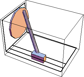
Mech graphics functions also operate without regard to the use of generalized coordinates. The following graphics object will generate the same image with any of the three constraint formulations used in the preceding example. Here is the graphics object representing the space-crank model. This shows the graphic at T = 0.15.
Out[72]= |  |
11.2 Loads and ReactionsThis section deals with issues related to applying loads to mechanisms modeled with generalized coordinates, and finding the reaction forces associated with those coordinates. 11.2.1 Applied LoadsUsing generalized coordinates has almost no effect on the modeling of applied loads. The standard Mech load functions Force, Moment, Gravity, and GyroMoment are used to apply loads to a generalized coordinate slave body in exactly the same way as they are used with standard bodies. The one load function that is affected by the use of generalized coordinates is Load, which is used to apply a load directly to a specified coordinate.
Since Load references the coordinates in a model directly by their symbolic name, it can be used to apply a load directly to a generalized coordinate. Conversely, Load cannot be used to apply a load directly to a Cartesian coordinate of a slave body because a slave body doesn't have any explicit Cartesian coordinates.
For example, suppose a model has two bodies, 2 and 3, and body 3 is a slave to body 2. The two bodies are joined by a revolute joint and the symbol alpha represents the rotation of the slave, relative to the master. The Force function may be used to apply a force in the global X direction to the slave, but the Load function may not. This loads the Modeler2D packages and defines names for bodies 2 and 3. Here is a load object that applies a 10-unit force to the slave body.
Out[4]= |  |
This load object does not apply the 10-unit force to the slave body, because X3 is not a coordinate in the model.
Out[5]= |  |
However, the Load function can be used to apply a moment to the slave body because the generalized coordinate alpha is an angular coordinate. A load applied directly to alpha essentially applies a counterclockwise moment to the slave body, and a clockwise moment to the master. Here is a load object that applies a 10-unit moment to the slave, and an equal and opposite moment to the master.
Out[6]= |  |
Here is a simpler load object that applies the same 10-unit couple between the slave and master.
Out[7]= |  |
In general, the Load function should be used instead of Force or Moment whenever possible because the resulting algebraic expressions that are added to the model can be much simpler. 11.2.2 Constraint ReactionsWhile the use of generalized coordinates has little effect on the application of loads to a model, finding constraint reaction forces is another matter. When a constraint is eliminated from a model by using generalized coordinates, information regarding the reaction forces at the constraint is lost. This is one basic disadvantage of a reduced coordinate system; by algebraically eliminating coordinates from a model we lose information about those coordinates.
Thus, three restrictions are placed on models using generalized coordinates: the Reaction function cannot be used to find the reaction forces applied by a generalized coordinate constraint to any body (because it is not really a constraint), the Reaction function cannot be used to find the reaction forces applied by any constraint to a generalized coordinate slave body (because the body doesn't have Cartesian coordinates), and the Loads function cannot be used to find the loads applied to a slave body (for the same reason).
Both the Reaction and Loads functions may still be used with generalized coordinates, but they must be used to access the coordinates directly.

Alternate usages of Reaction and Loads. The physical meaning of the quantities returned by Reaction and Loads is quite clear, in the context of the simple generalized coordinate constraints. If the generalized coordinate sym represents an angle in radians, then the loads on the coordinate are in consistent units of moment. If the coordinate sym represents a distance, then the loads on the coordinate are in consistent units of force.
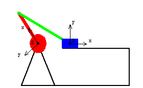
However, if abstract user-defined generalized coordinate constraints are used, the generalized loads may have little physical meaning, just like the generalized loads associated with each constraint ( 1, 1,  2, ...) sometimes have little physical meaning. The one meaning that always applies to a generalized load is this: a generalized load multiplied by a small variation in its associated generalized coordinate is equal to a small variation in work, in consistent energy units. 2, ...) sometimes have little physical meaning. The one meaning that always applies to a generalized load is this: a generalized load multiplied by a small variation in its associated generalized coordinate is equal to a small variation in work, in consistent energy units. 11.2.3 Slider-Crank Example MechanismTo demonstrate the use of the Reaction and Loads functions with generalized coordinates a planar model of a simple slider-crank mechanism is developed. This model uses only two bodies, the slider and crank, and it is modeled with two generalized coordinates, the rotation angle of the crank and the X displacement of the slider. This loads the Modeler2D packages and defines some useful constants. Here is the slider-crank mechanism.
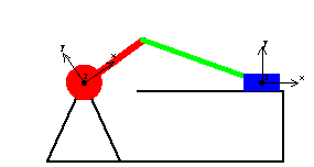
Bodies Two body objects are defined for the slider-crank model. Inertia properties are defined for each moving body so that the dynamic reaction forces can be calculated. No local point definitions are made in the body objects. All necessary point coordinates in this model are given explicitly in the constraint functions. Here are the body objects for the slider-crank model. The body properties are incorporated into the model. ConstraintsFour constraints are used to model the slider-crank mechanism. Two generalized coordinate constraints are used along with two standard constraints. A GenRevolute2 constraint defines the symbol alpha as the angular coordinate of the crank.A RotationLock1 constraint controls the rotation of the crank.A GenTranslate2 constraint defines the symbol beta as the displacement coordinate of the slider.A RelativeDistance1 constraint models the connecting rod between the crank and the slider.Here are the constraint objects for the slider-crank mechanism. The constraints are incorporated into the current model. LoadsA force that is a linear function of slider position is applied to the slider to simulate a simple spring. The spring has a spring constant of 10, and it is placed so that the spring force is zero when the X displacement of the slider is three units. Here is a spring force applied to the slider. The model is run at T = 0.1 with the Static option to cause the Lagrange multipliers to be calculated.
Out[22]= |  |
ReactionsBecause generalized coordinates were used in this model, Mech's ability to find constraint reaction forces is limited. Normally, Reaction could be used to find the reaction force vector that the revolute joint applies to the crank, but with this model only the moment applied to the crank by constraint 2 can be found. Note that Reaction cannot directly find the moment applied to body 2, it can only find the generalized force associated with the symbol alpha. Since alpha is an angular coordinate, its associated load is a moment. Here is the moment applied to the crank by the driving constraint.
Out[23]= |  |
Of course constraint 4, the RelativeDistance1 constraint, applies an equal and opposite moment to the crank. Here is the moment applied to the crank by the connecting rod.
Out[24]= |  |
Out[25]= |  |
Constraint 4 also applies a reaction force to the slider. Again, the restraining force and torque that would be applied to the slider by a normal Translate2 constraint cannot be found. Only the generalized force associated with beta can be found, which is the X direction force on the slider. Here is the force applied to the slider by the connecting rod.
Out[26]= |  |
Here are the external loads applied to the coordinates alpha and beta.
Out[27]= |  |
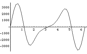
The inertia terms are automatically converted into the proper coordinate system so that the dynamic reaction forces may be calculated. The Solution -> Dynamic option causes SolveMech to include the inertial loads and calculate the reaction forces. Here is a plot of the torque required to drive the crank through a full cycle.
Out[28]= |  |
Here is the graphics function that generates the image of the slider-crank mechanism. Here is the slider-crank mechanism at T = 0.35.
Out[30]= |  |
11.3 Dynamic ModelingThis section covers topics related to generalized coordinate modeling of dynamic systems. Dynamic motion synthesis is often where generalized coordinates have their greatest payoff. Using a coordinate system that is closer to being a minimal and independent set can drastically reduce the size of the mass matrix and centrifugal force vector, resulting in reduced runtimes for the numerical integration routine.
The reduced mass matrix, in terms of generalized coordinates, is often useful in its own right for certain types of analysis. Examples of various mass matrix manipulations are presented in this section, including the conversion of an open-loop mass matrix to endpoint coordinates, and the reduction of a closed loop mass matrix to minimal coordinates. 11.3.1 Two-Link Manipulator ExampleIt is often useful to find the mass matrix of a model with respect to an alternative coordinate system. When generalized coordinates are used, Mech automatically generates the model's mass matrix in terms of the specified coordinates, and converting the mass matrix to another consistent coordinate system is a straightforward process.
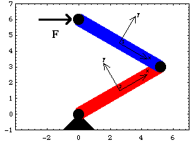
An open-loop two-link manipulator model is developed to demonstrate the conversion of a mass matrix from one coordinate system to another. The model has two moving bodies, link 1 and link 2, which are represented by two generalized coordinates, alpha and beta. The alpha coordinate represents the rotation angle of link 1 relative to the ground and beta represents the rotation of link 2 relative to link 1. This loads the Modeler2D packages and defines some useful constants. Here is a graphic of the two-link manipulator model.
Bodies Two body objects are used in the manipulator model. Each body object is used only to define inertia properties for the body, no local point definitions are made. Thus the ground (body 1) needs no body object because its inertia is immaterial. Note that the lengths of the links are left as parameters L1 and L2, causing the resulting mass matrix to be completely general. Here are the body objects for the manipulator model. The inertia properties are incorporated into the model. ConstraintsFour constraint objects are used to model the manipulator. Two constraints are generalized coordinate constraints that introduce the two degrees of freedom, alpha and beta, and the other two constraints simply constrain these two degrees of freedom. A GenRevolute2 constraint sets up the relationship between link 1 and the ground.A GenRevolute2 constraint sets up the relationship between link 2 and link 1.Two Constraint objects constrain alpha and beta to be equal to the parameters q1 and q2.Note that L1 appears explicitly in constraint 3 to locate the tip of link 1 where it is attached to link 2. Here are the constraint objects for the manipulator. The constraints are incorporated into the current model. Mass MatrixThe kinematics of this model are truly trivial. The entire constraint set is nothing more than a pair of expressions setting alpha and beta equal to q1 and q2. There is really no point in running the model at all, in the normal sense in which other Mech models are run because the configuration of the model can be specified directly by alpha and beta. The usefulness of the model lies in the other definitions that have been made by Mech for inertia properties and coordinate transformations. Here is the constraint vector.
Out[16]= |  |
Here is the global location of the tip of link 2.
Out[17]= |  |
Here is the  system mass matrix. system mass matrix.
Out[18]= |  |
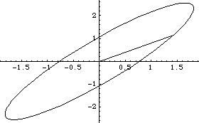
Endpoint MobilityNow we wish to find the ellipse of mobility of the endpoint of link 2. The ellipse of mobility of an equivalent two-link manipulator model was found in Section 10.3. In that example, a one-unit force was applied to the endpoint of link 2 while varying the direction of the force through 360 degrees, and the resulting free acceleration vector of the endpoint was found with the SetFree and SolveFree functions.
This section presents a more elegant method of finding the ellipse of mobility directly from the mass matrix. The method presented in Section 10.3 is much more general than this one in that this method (as it is presented here) is restricted to finding the mobility of the endpoint at zero velocity, and is restricted to models that have the same total number of coordinates as the number of physical degrees of freedom of the endpoint.
The basic trick here is to convert the mass matrix from the generalized (joint angle) coordinates to endpoint coordinates. The mass matrix m, in the context of  , transforms accelerations of the generalized coordinates a, which are the relative angular accelerations of each of the joints, into forces on the generalized coordinates f, which are moments applied at the joints. We need to have a matrix P in , transforms accelerations of the generalized coordinates a, which are the relative angular accelerations of each of the joints, into forces on the generalized coordinates f, which are moments applied at the joints. We need to have a matrix P in  , which transforms a force vector F applied to the endpoint into the linear acceleration vector A of the endpoint. First, we need a transformation matrix J from generalized coordinates to endpoint coordinates such that , which transforms a force vector F applied to the endpoint into the linear acceleration vector A of the endpoint. First, we need a transformation matrix J from generalized coordinates to endpoint coordinates such that  . Then . Then  . .
The matrix J is the Jacobian of the global coordinates of the endpoint. Here is the transformation matrix J.
Out[19]= |  |
Here is the inverse endpoint mass matrix P, a rather large symbolic matrix. We can now find the acceleration of the endpoint that results from any force vector at any particular configuration simply by multiplying P times the force vector. Here is the acceleration vector resulting from an applied force {0, 2}.
Out[22]= |  |
Now finding the ellipse of mobility is simply a matter of applying a unit force vector that revolves through a full circle and plotting the components of the resulting acceleration. Here is the ellipse of mobility.
Out[23]= |  |
11.3.2 Four-Bar ExampleAnother useful manipulation of the mass matrix is to find a minimal mass matrix for a model with a nonminimal coordinate system. While this can theoretically be done with or without generalized coordinates, it often becomes intractable when modeling in Cartesian coordinates because of the need to invert a large symbolic matrix.
The four-bar model that was developed previously in this section is used again here to demonstrate the formulation of a minimal mass matrix. In this case, the minimal mass matrix is a  matrix because the four-bar model has only one degree of freedom. Since the four-bar mechanism is modeled with three generalized coordinates alpha, beta, and gamma, the default mass matrix generated by Mech is a matrix because the four-bar model has only one degree of freedom. Since the four-bar mechanism is modeled with three generalized coordinates alpha, beta, and gamma, the default mass matrix generated by Mech is a  matrix; the task at hand is to reduce it to matrix; the task at hand is to reduce it to  . Note that inertia properties are included in the body objects of this version of the four-bar. . Note that inertia properties are included in the body objects of this version of the four-bar. This clears all data in the current Mech model. Bodies and ConstraintsThe entire four-bar model is redefined without explanation here, because its kinematics are completely documented in Section 8.3.2. Here are the body objects for the four-bar model. Here are the generalized coordinate constraint objects. Mass MatrixWe intend to transform the  system mass matrix M into a system mass matrix M into a  mass matrix m where mass matrix m where  and f is the generalized force in the direction of alpha, which is simply a counterclockwise moment applied to the drive bar. This transformation is of the form and f is the generalized force in the direction of alpha, which is simply a counterclockwise moment applied to the drive bar. This transformation is of the form  . .
The necessary transformation matrix J converts motions in all three generalized coordinates into motions of the single coordinate alpha. This matrix J is created by inverting the part of the model's Jacobian associated with beta and gamma and multiplying it by the part associated with alpha. The resulting 2x1 matrix converts alpha only into beta and gamma, so it must be prepended with a 1 to convert alpha into all three coordinates.
Only the part of the Jacobian associated with constraint 5 is included in the calculation because the driving constraint (constraint 1) must be dropped for the model to have more than zero degrees of freedom, and the other three generalized coordinate constraints contribute no constraint equations. Here is the  transformation matrix J. transformation matrix J. Here is the  system mass matrix. system mass matrix.
Out[28]= |  |
Here is the  mass matrix in terms of the coordinate alpha. mass matrix in terms of the coordinate alpha. Since m is a  matrix it may as well be a scalar, and the acceleration that results from applying a moment to the drive bar is simply matrix it may as well be a scalar, and the acceleration that results from applying a moment to the drive bar is simply  . Remember that m is still a function of alpha, beta, and gamma, and not just any set of alpha, beta and gamma will do (unlike the two-link manipulator in which any values of the coordinates could be specified). SolveMech must be used to find a set of coordinates that represents a valid configuration of the four-bar model. . Remember that m is still a function of alpha, beta, and gamma, and not just any set of alpha, beta and gamma will do (unlike the two-link manipulator in which any values of the coordinates could be specified). SolveMech must be used to find a set of coordinates that represents a valid configuration of the four-bar model. The  matrix m is converted to a scalar. matrix m is converted to a scalar. Here is the configuration of the four-bar model at 1/8 turn of the drive bar.
Out[31]= |  |
Here is the acceleration that results from a 10-unit moment applied to the drive bar.
Out[32]= |  |
Dynamic MotionThe constrained dynamic motion profile of the four-bar model can be found with the SetFree and SolveFree functions, as described in Chapter 10. In this example, the drive bar is given an initial angular velocity of 2 pi radians/second, a condition that is inherent in the definition of constraint 1. Constraint 1 is dropped from the model, and the free motion of the underconstrained system is found. The model is run at T = 0 to make initial conditions available to SetFree. Here is the FreeSystem object that contains the dynamical equations of motion, with constraint 1 dropped.
Out[34]= |  |
The FreeSystem object fsys is integrated in the time domain from T = 0.0 to 2.0 with SolveFree. All initial conditions for the integration are taken from the most recent solution returned by SolveMech. Here is the time domain solution.
Out[35]= |  |
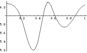
Here is a plot of the angular velocity of the drive bar through approximately one full revolution of the drive bar.
Out[36]= |  |
|