Since one element of the Perron-Frobenius eigenvector can always be normalized, that is, set equal to 1 at all frequencies, it is often useful to plot the behavior of the other elements after this normalization, and consider the possibly simpler dynamic scaling compensator that may result. The option NormalizedElement can be used with the functions PerronFrobeniusEigenvectorPlot (see Section 5.3.2), and PerronFrobeniusCompensator (see Sections 5.3.1 and 5.3.2) for this purpose. | option name | default value | | | NormalizedElement | None | which element to normalize |
Normalizing an element of the dynamic Perron-Frobenius compensator. Make sure the application is loaded. This is the two-input, two-output transfer-function object, considered in Section 5.3.2. | Out[3]= |  |
This plots the behavior of element 2 of the Perron-Frobenius right eigenvector, with element 1 normalized. 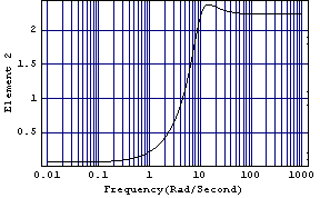
This plots the behavior of element 1 of the Perron-Frobenius right eigenvector, with element 2 normalized. 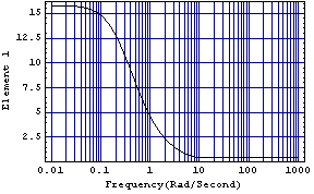
Since the second plot has the simpler frequency response, namely, that of a phase-retard compensator, normalizing the second element in the function PerronFrobeniusCompensator may lead to a simpler dynamic compensator. This determines a dynamic compensator with numerator and denominator of order 1. | Out[7]= |  |
This is a plot of the amplitude behavior of its nonconstant term. 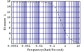
Clearly, the first-order compensator provides a good fit to the behavior of the Perron-Frobenius eigenvector. 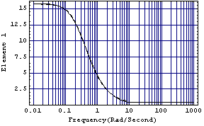
This applies the compensator to the system. The compensator provides reasonable dominance ratios, especially at the low frequencies. 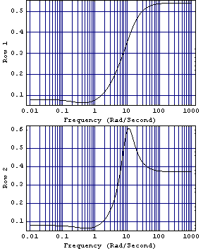
This scales up row 2 of the Nyquist array to give a more clear plot. Here is the resulting Nyquist array. 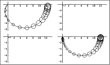
Since this simpler compensator has achieved a very good level of diagonal dominance in both diagonal terms of the resulting Nyquist array, the designer may choose to use this instead of the more complex compensator determined earlier. This is the closed-loop system with the first-order dynamic Perron-Frobenius compensator. Here are the step responses of the closed-loop system. 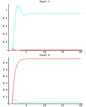
Both plots exhibit an acceptably small level of interaction and possibly significant steady-state errors, with a potentially unacceptable level of overshoot in the first loop. However, since the system is diagonal dominant, each control loop can now be addressed separately, and simple PI action controllers can be introduced into each control loop to further improve these responses (see the example in Section 5.4.3). |