|
3.8.8 ApproximateDeterminant

Command structure of ApproximateDeterminant.
With ApproximateDeterminant you can approximate a linear symbolic matrix equation  directly with respect to a particular eigenvalue directly with respect to a particular eigenvalue  (a pole or a zero). By discarding all terms which have little or no influence on (a pole or a zero). By discarding all terms which have little or no influence on  , ApproximateDeterminant reduces both the complexity and the degree of the characteristic polynomial , ApproximateDeterminant reduces both the complexity and the degree of the characteristic polynomial  . Provided that the eigenvalue of interest is located sufficiently far apart from other eigenvalues, the polynomial degree can be reduced to . Provided that the eigenvalue of interest is located sufficiently far apart from other eigenvalues, the polynomial degree can be reduced to  if if  is real or is real or  if if  is complex. The argument dae must be an AC DAEObject written in matrix form (see CircuitEquations in Section 3.5.1). is complex. The argument dae must be an AC DAEObject written in matrix form (see CircuitEquations in Section 3.5.1).
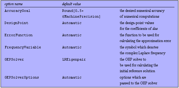
The following options can be used with ApproximateDeterminant:

Options for ApproximateDeterminant, Part I.

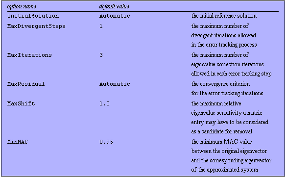
Options for ApproximateDeterminant, Part II.

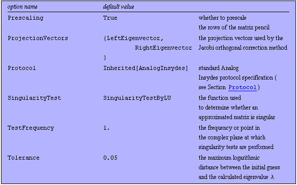
Options for ApproximateDeterminant, Part III.
See also: GeneralizedEigensystem, LREigenpair.
Options Description
A detailed description of all ApproximateDeterminant options is given below in alphabetical order:
AccuracyGoal
AccuracyGoal -> n specifies the desired accuracy of the sought eigenvalue in terms of the number of accurate significant digits. The value of AccuracyGoal is used to determine an appropriate setting for the MaxResidual option if MaxResidual -> Automatic. See also LREigenpair.
DesignPoint
With DesignPoint -> dp, you can specify a list of design-point values for the coefficients of a symbolic system of circuit equations. The default setting DesignPoint -> Automatic causes ApproximateDeterminant to use the design-point information stored in dae. You can use the DesignPoint option to override design-point data stored in dae.
ErrorFunction
ErrorFunction -> func specifies the function to be used for calculating the error of an approximated eigenvalue with respect to the reference solution. The following values are allowed:

Values for the ErrorFunction option.
FrequencyVariable
ApproximateDeterminant needs to know the symbol which represents the complex frequency in order to be able to decompose the system of circuit equations dae into the matrices  and and  . With FrequencyVariable -> Automatic, the symbol is determined automatically from the status information stored in dae. You can specify the frequency variable manually with FrequencyVariable -> var. . With FrequencyVariable -> Automatic, the symbol is determined automatically from the status information stored in dae. You can specify the frequency variable manually with FrequencyVariable -> var.
GEPSolver
With GEPSolver -> func, you can select the GEP solver ApproximateDeterminant uses to calculate the initial reference solution. Possible option values are:

Values for the GEPSolver option.
GEPSolverOptions
With GEPSolverOptions -> opts, you can specify a list of option settings that will be passed to the selected GEP solver, for example:
GEPSolverOptions -> {MaxResidual -> 1.*^-7,
MaxIterations -> 100}
Note that you may also change the option settings of the selected GEP solver directly with SetOptions[gepsolver, opts]. However, with GEPSolverOptions, you can specify private option settings which will only be used in conjunction with ApproximateDeterminant.
InitialSolution
With InitialSolution -> initsol, you can specify the initial reference solution for the GEP to be approximated. The value of InitialSolution must be given in the same format as the return value of LREigenpair. Possible values are:

Values for the InitialSolution option.
MaxDivergentSteps
MaxDivergentSteps -> n specifies the maximum number of divergent iterations allowed in the error tracking step following the elimination of a matrix entry. Iterates are considered divergent if the residual of the numerical solution of the GEP becomes larger between two consecutive steps. If the number of divergent steps exceeds the specified maximum in the error tracking process, ApproximateDeterminant aborts the iterations, reinserts the current term into the matrix, and continues with the next term.
MaxIterations
MaxIterations -> n specifies the maximum number of error tracking iterations performed after removing a matrix entry. An approximation is considered valid if the iterations converge within  steps, and if both the MaxResidual and MinMAC specifications are satisfied. See also LREigenpair. steps, and if both the MaxResidual and MinMAC specifications are satisfied. See also LREigenpair.
 MaxResidual
 -> posreal specifies the convergence criterion for the error tracking iterations. MaxResidual is one of the key options you should play with in order to obtain good results from ApproximateDeterminant. You should choose the value as large as possible to allow for a reasonable error but small enough to prevent the iterations from "converging" to an arbitrary value. This may require some experimentation. See also LREigenpair.
 MaxShift
 -> posreal restricts the list of matrix entries which are candidates for removal to those entries with a eigenvalue sensitivity figure less than posreal. With MaxShift -> 1.0, a term will be considered for removal if the eigenvalue shift caused by removing the term has been predicted to be less than  . To restrict the list of matrix entries to terms with small eigenvalue sensitivities, use a setting such as MaxShift -> 0.1. . To restrict the list of matrix entries to terms with small eigenvalue sensitivities, use a setting such as MaxShift -> 0.1.
MinMAC
MinMAC -> posreal specifies the minimum allowed value of the modal assurance criterion between the right eigenvector of the original GEP,  , and the right eigenvector of the approximated GEP, , and the right eigenvector of the approximated GEP,  . The MAC between . The MAC between  and and  constitutes a measure for the correlation of the two eigenvectors. It is defined as constitutes a measure for the correlation of the two eigenvectors. It is defined as

The value of the MAC ranges from  to to  . A value of . A value of  means that one eigenvector is a multiple of the other. A value of means that one eigenvector is a multiple of the other. A value of  means that the two vectors are completely uncorrelated. means that the two vectors are completely uncorrelated.
The use of the MAC helps to prevent ApproximateDeterminant from accidentally converging to some other eigenvalue than the one of interest. For corresponding eigenpairs of the original and approximated GEP, the value of the MAC should be close to  , say , say  , whereas the MAC between the eigenvector of the original GEP and some other eigenvector of the approximated system should be small. ApproximateDeterminant considers an approximation step as invalid if the MAC between the two eigenvectors falls below the value of MinMAC. , whereas the MAC between the eigenvector of the original GEP and some other eigenvector of the approximated system should be small. ApproximateDeterminant considers an approximation step as invalid if the MAC between the two eigenvectors falls below the value of MinMAC.
Prescaling
With Prescaling -> True, ApproximateDeterminant scales the rows of the matrix pencil  such that the absolute value of the largest coefficient in each row is 1. In general, prescaling improves the numerical properties of ill-conditioned GEPs and helps to reduce the number of iterations. Prescaling does not change the eigenvalues and eigenvectors of the matrix pencil. You can turn off prescaling by setting Prescaling -> False. such that the absolute value of the largest coefficient in each row is 1. In general, prescaling improves the numerical properties of ill-conditioned GEPs and helps to reduce the number of iterations. Prescaling does not change the eigenvalues and eigenvectors of the matrix pencil. You can turn off prescaling by setting Prescaling -> False.
 ProjectionVectors
With the option ProjectionVectors -> {wt, yt}, you can choose the vectors ApproximateDeterminant uses as projection vectors for the Jacobi orthogonal correction method (JOCM) during error tracking operations:
Starting with a given initial guess  for the sought eigenvalue and eigenvectors, the JOCM repeatedly solves the correction equation for the sought eigenvalue and eigenvectors, the JOCM repeatedly solves the correction equation

for updates  of of  and and  . The symbols . The symbols  and and  denote two arbitrary projection vectors, which must be chosen appropriately in each step to ensure convergence of the iterates. Suitable choices for denote two arbitrary projection vectors, which must be chosen appropriately in each step to ensure convergence of the iterates. Suitable choices for  and and  include combinations of the initial guesses and the most recent approximations of the eigenvectors include combinations of the initial guesses and the most recent approximations of the eigenvectors  and and  . .
Possible settings for the ProjectionVectors option are:

Values for the ProjectionVectors option.
In most cases, the default setting ProjectionVectors -> {LeftEigenvector, RightEigenvector} constitutes an appropriate choice. You will need to change the setting of this option only if you encounter convergence problems. See also Section 3.8.7.
 SingularityTest
After each approximation step, ApproximateDeterminant applies a singularity test to the matrix  to ensure that removing a matrix entry has not rendered the GEP singular. The singularity test is performed by numerical computation of the rank of to ensure that removing a matrix entry has not rendered the GEP singular. The singularity test is performed by numerical computation of the rank of  for some for some  which is not an eigenvalue of the GEP. However, there is no guarantee that numerical rank computation always yields a mathematically correct result. This may cause singularity to remain undetected in some situations, particularly when the GEP is ill-conditioned. With the option SingularityTest, you can select the function ApproximateDeterminant uses to determine whether the GEP is singular. If you encounter singularity problems, i.e. if which is not an eigenvalue of the GEP. However, there is no guarantee that numerical rank computation always yields a mathematically correct result. This may cause singularity to remain undetected in some situations, particularly when the GEP is ill-conditioned. With the option SingularityTest, you can select the function ApproximateDeterminant uses to determine whether the GEP is singular. If you encounter singularity problems, i.e. if  after approximating a system of circuit equations, then you should change the value of SingularityTest and rerun the approximation. after approximating a system of circuit equations, then you should change the value of SingularityTest and rerun the approximation.
The possible values for SingularityTest are:

Values for the SingularityTest option.
TestFrequency
With the option TestFrequency, you can specify the value of the complex frequency variable  which is used for testing whether the numerical matrix which is used for testing whether the numerical matrix  is singular. For best numerical accuracy and computing performance, it is recommended that you choose a real value of the same order of magnitude as the modulus of the target eigenvalue. For example, if you wish to approximate a GEP with respect to an eigenvalue is singular. For best numerical accuracy and computing performance, it is recommended that you choose a real value of the same order of magnitude as the modulus of the target eigenvalue. For example, if you wish to approximate a GEP with respect to an eigenvalue  , then the option setting TestFrequency -> 1.0*^8 constitutes an appropriate choice. , then the option setting TestFrequency -> 1.0*^8 constitutes an appropriate choice.
 Tolerance
 -> tol specifies the radius of the tolerance region around the initial guess theta0 in which the sought eigenvalue  should lie. ApproximateDeterminant generates a warning if it converges to an eigenvalue that lies outside the tolerance region. The Tolerance option allows you to check whether ApproximateDeterminant has found the eigenvalue you wished to compute or whether the iterations have converged to a completely different solution. should lie. ApproximateDeterminant generates a warning if it converges to an eigenvalue that lies outside the tolerance region. The Tolerance option allows you to check whether ApproximateDeterminant has found the eigenvalue you wished to compute or whether the iterations have converged to a completely different solution.
Tolerance uses a logarithmic measure for distances. For example, Tolerance -> 1.0 allows the value of the solution  to lie within to lie within  and and  times the value of the initial guess theta0. times the value of the initial guess theta0.
Examples
Load Analog Insydes.
In[1]:= <<AnalogInsydes`
Define an AC model for BJTs.
In[2]:= Circuit[
Model[
Name -> BJT,
Selector -> AC,
Scope -> Global,
Ports -> {B, C, E},
Parameters -> {Rbe, Cbc, Cbe, beta, Ro,
RBE, CBC, CBE, BETA, RO},
Definition -> Netlist[
{CBE, {B, E}, Symbolic -> Cbe, Value -> CBE},
{RBE, {X, E}, Symbolic -> Rbe, Value -> RBE},
{CBC, {B, C}, Symbolic -> Cbc, Value -> CBC},
{CC, {B, X, C, E},
Symbolic -> beta, Value -> BETA},
{RO, {C, E}, Symbolic -> Ro, Value -> RO}
]
]
] // ExpandSubcircuits;
This netlist describes a common-emitter amplifier.
In[3]:= ceamplifier =
Circuit[
Netlist[
{V1, {1, 0}, 1},
{V0, {6, 0}, 0},
{C1, {1, 2}, Symbolic -> C1, Value -> 1.0*^-7},
{R1, {2, 6}, Symbolic -> R1, Value -> 1.0*^5},
{R2, {2, 0}, Symbolic -> R2, Value -> 47000.},
{RC, {6, 3}, Symbolic -> RC, Value -> 2200.},
{RE, {4, 0}, Symbolic -> RE, Value -> 1000.},
{C2, {3, 5}, Symbolic -> C2, Value -> 1.0*^-6},
{RL, {5, 0}, Symbolic -> RL, Value -> 47000.},
{Q1, {2 -> B, 3 -> C, 4 -> E},
Model -> BJT, Selector -> AC,
CBE -> 30.*^-12, CBC -> 5.*^-12, RBE -> 1000.,
RO -> 10000., BETA -> 200.}
]
]
Out[3]= 
Set up system of symbolic AC equations.
In[4]:= eqs = CircuitEquations[ceamplifier,
ElementValues -> Symbolic]
Out[4]= 
Calculate poles and zeros of the voltage transfer function.
In[5]:= pz = PolesAndZerosByQZ[eqs, V$5]
Out[5]= 
Show the pole/zero distribution.
In[6]:= RootLocusPlot[pz, LinearRegionLimit -> 100,
PlotRange -> 5.0*^10]

Out[6]= 
The numerical pole/zero analysis shows that the characteristic polynomial of the equations has a degree of four because the amplifier has four poles. Although polynomial equations with a degree up to four can be solved analytically, the resulting expressions are usually very complex if the degree is greater than two. Therefore, we use ApproximateDeterminant to compute simplified formulas for the poles.
We begin by computing an approximate expression for the pole near  . The logarithmic error bound specification . The logarithmic error bound specification  corresponds to a tolerance region from corresponds to a tolerance region from  to to  of the design-point value of the design-point value  . .
Approximate the equations with respect to  using the QZ algorithm for computing the reference solution. using the QZ algorithm for computing the reference solution.
In[7]:= sbgp2 = ApproximateDeterminant[eqs, -400, 0.05,
MaxIterations -> 4, GEPSolver -> GeneralizedEigensystem]
Out[7]= 
To check if the algorithm has successfully isolated the pole of interest, we compute the poles of the approximated system.
Compute the remaining poles numerically.
In[8]:= PolesByQZ[sbgp2]
Out[8]= 
Estimate the number of remaining terms.
In[9]:= ComplexityEstimate[sbgp2]
Out[9]= 
Show complexity of original system.
In[10]:= ComplexityEstimate[eqs]
Out[10]= 
The result shows that the algorithm has eliminated the two high-frequency poles and has approximated the low-frequency pole  near near  by zero. On the contrary, the pole by zero. On the contrary, the pole  has been preserved, and its numerical value lies in the specified tolerance region. In addition, the complexity of the characteristic polynomial has been greatly reduced. Therefore, we can expect to obtain an interpretable formula for has been preserved, and its numerical value lies in the specified tolerance region. In addition, the complexity of the characteristic polynomial has been greatly reduced. Therefore, we can expect to obtain an interpretable formula for  . .
Compute the approximated characteristic polynomial.
In[11]:= detp2 = Det[GetMatrix[sbgp2]] // Together
Out[11]= 
Solve for the poles.
In[12]:= sbgpoles = Solve[detp2 == 0, s]
Out[12]= 
Extract the pole of interest.
In[13]:= p2 = s /. Last[sbgpoles] // Simplify
Out[13]= 
Next, we try to extract the right-half plane zero  near near  . .
Approximate the equations with respect to  . .
In[14]:= sbgz3 = ApproximateDeterminant[eqs, V$5, 2.0*^8, 0.05,
GEPSolver -> GeneralizedEigensystem]
Out[14]= 
Compute the remaining zeros numerically.
In[15]:= ZerosByQZ[sbgz3, V$5]
Out[15]= 
Compute the approximated polynomial.
In[16]:= detz3 = Det[GetMatrix[sbgz3]] // Simplify
Out[16]= 
Solve for the zeros.
In[17]:= sbgzeros = Solve[detz3 == 0, s]
Out[17]= 
Extract the zero of interest.
In[18]:= z3 = s /. Last[sbgzeros]
Out[18]= 
|