|
2.9.5 Two-Port Parameters
Two-Port Representations
It is easy to extend the analysis procedures for computing transfer functions to two-port parameter analysis because two-port or, more generally, n-port matrices can be regarded as transfer functions in several dimensions. Indeed, every single coefficient in a two-port matrix is a transfer function from one port current or voltage to another, so we could obtain the four coefficients of a two-port matrix by means of four separate transfer function analyses. However, we will apply a more efficient strategy which allows for calculating complete n-port matrices in only one step.
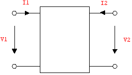
Figure 9.8: Two-port current and voltage reference directions
Figure 9.8 shows the voltages and currents at the terminals of a two port. The relation between the port quantities  , ,  , ,  , and , and  is generally given as a linear mapping of two equations in four variables: is generally given as a linear mapping of two equations in four variables:

Solving these equations for any combination of two-port voltages or currents yields one of six possible two-port representations known as the admittance, impedance, hybrid I and II, and cascade I and II forms. For example, solving for  and and  in terms of in terms of  and and  results in the admittance, or Y-matrix, representation results in the admittance, or Y-matrix, representation

whose coefficients  are known as the Y-parameters of the two port. Similarly, solving for are known as the Y-parameters of the two port. Similarly, solving for  and and  in terms of in terms of  and and  yields the impedance, or Z-matrix, representation: yields the impedance, or Z-matrix, representation:

Stimulus Sources for Two-Port Calculations
A particular two-port matrix can be computed by connecting appropriate stimulus sources to the ports and solving for the opposite port quantities. For instance, if we want to compute a Z-matrix we must connect current sources to the ports, set up circuit equations and solve for the corresponding port voltages. Likewise, a Y-matrix is obtained by connecting voltage sources V1 and V2 to the ports and determining the port currents I$V1 and I$V2 in terms of these voltages.
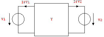
Figure 9.9: Voltage source excitation for Y-matrix calculation
Note that a straightforward combination of the two-port circuit and the excitation sources as shown in Figure 9.9 will not yield an entirely correct result. The resulting Y-parameters would have a wrong sign because the positive reference directions for the branch currents of the voltage sources are not oriented according to the reference directions for two-port terminal currents.
Remember that the positive reference direction for the current and voltage in a circuit branch is always determined by the order of the nodes in the corresponding netlist entry (see Chapter 2.2).
The reference direction for the port currents can be aligned with the two-port terminal current directions by reversing the order of the nodes in the netlist entries belonging to the stimulus sources. However, the voltage reference directions, whose initial settings were correct, are changed by this operation as well. Hence, to compensate this unwanted effect, the voltages must be given negative values in the netlist (see Figure 9.10).
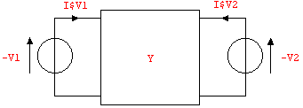
Figure 9.10: Correct voltage source excitation for computing Y-parameters
Computing Y-Parameters
Let's demonstrate the procedure for two-port analysis by calculating the Y-matrix of the circuit shown in Figure 9.11.
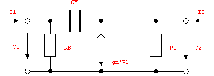
Figure 9.11: Two-port circuit
As discussed in the preceding subsection we must connect stimulus voltage sources to the circuit as shown in Figure 9.12 and write the corresponding netlist. If you want to calculate two-port parameters of a circuit whose netlist was read by ReadNetlist, you can use DeleteElements and AddElements to edit the netlist.
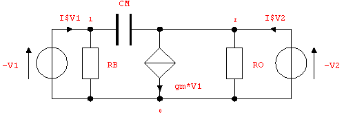
Figure 9.12: Correct voltage source excitation for computing Y-parameters
In[24]:= twoport =
Netlist[
{V1, {0, 1}, -V1},
{V2, {0, 2}, -V2},
{RB, {1, 0}, RB},
{CM, {1, 2}, CM},
{VC1, {1, 0, 2, 0}, gm},
{RO, {2, 0}, RO}
]
Out[26]= 
Next, we set up a system of circuit equations and compute the port currents I$V1 and I$V2 as functions of the stimulus voltages V1 and V2.
In[25]:= twoportmna = CircuitEquations[twoport];
DisplayForm[twoportmna]
Out[28]//DisplayForm= 
In[26]:= ypar = Solve[twoportmna, {I$V1, I$V2}]
Out[29]= 
The Y-parameters of the two-port circuit are given by the coefficients of V1 and V2 on the right-hand sides of the solutions.
In[27]:= yrhs = {I$V1, I$V2} /. First[ypar];
MatrixForm[yrhs]
Out[31]//MatrixForm= 
To set up the Y-matrix we must extract the coefficient matrix from these two linear expressions, for example by computing the Jacobian with respect to V1 and V2.
In[28]:= JacobianMatrix[eqs_, vars_] := Outer[D, eqs, vars]
In[29]:= ymatrix = JacobianMatrix[yrhs, {V1, V2}];
MatrixForm[ymatrix]
Out[34]//MatrixForm= 
|