|
2.9.4 Input and Output Impedances
Circuit Configuration for Impedance Calculations
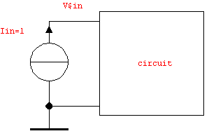
Since input and output impedances are transfer functions just like voltage gains we can compute the former using the same circuit analysis procedures as for any other transfer function. An input impedance is the transfer function from the current flowing into a port to the voltage across the same port (see Figure 9.6).

Figure 9.6: Unit current source excitation for input impedance calculations
Likewise, an input admittance is the transfer function from a voltage across the port to the current into the port. The same applies to output impedances and admittances which are, in fact, just the input impedances and admittances at a port which is designated as an output. Consequently, to calculate an output impedance we must connect a unit current source to the port, set up a system of circuit equations, and solve for the port voltage.
Computing the Output Impedance of the CMOS Amplifier
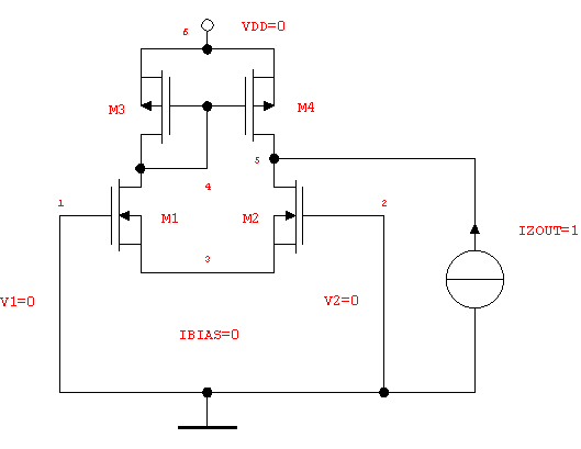
To determine the output impedance of the differential amplifier (see Figure 9.4 in Section 2.9.2) we replace the load capacitor by a stimulus current source as displayed in Figure 9.7.

Figure 9.7: Differential amplifier, small-signal configuration for computing the output impedance
Replacing the load capacitor is done by editing our via ReadNetlist imported netlist. Therefore, we first remove the netlist entry for CL using the Analog Insydes command DeleteElements and in a second step we add an independent current source IZ using the command AddElements.
In[19]:= cmosdiffamp2 = DeleteElements[cmosdiffamp, CL];
cmosdiffamp2 = AddElements[cmosdiffamp2,
{IZ, {0, 5}, IZout}];
After the modification of the netlist we set up the modified nodal equations and solve for the voltage at the output port, i.e. V$5.
In[20]:= mnaZout = CircuitEquations[cmosdiffamp2,
ElementValues -> Symbolic,
DefaultSelector -> LowFrequency]
Out[22]= 
In[21]:= zout = Together[V$5 /. First[Solve[mnaZout, V$5]]
/. {IBIAS -> 0, VDD -> 0, V1 -> 0, V2 -> 0, IZout -> 1}]
Out[23]= 
For matching the MOS transistors forming the differential pair and the current-mirror load we again apply the command MatchSymbols:
In[22]:= zoutmatch = Together @ MatchSymbols[zout,
{{"$M1", "$M2", "12"}, {"$M3", "$M4", "34"}}]
Out[24]= 
As usual, this expression contains many numerically small terms which are identified and discarded by ApproximateTransferFunction. The output impedance is then given by the following simple formula in terms of the drain-source conductances Gds12 and Gds34.
In[23]:= zoutSAG = ApproximateTransferFunction[
zoutmatch, s, dpcmos, 0.05] // Simplify
Out[25]= 
|