Using the state-feedback mapping algorithm proposed by Young and Willems (1972), the feedback matrix K that places the poles of a single-input system  at at  {1}, {1}, {2},..., {2},..., n can be found as n can be found as where  is the controllability matrix is the controllability matrix X is the lower Toeplitz matrix formed from the coefficients of the open-loop system characteristic polynomial and  is a vector whose coefficients are the difference between the coefficients of the desired closed-loop characteristic polynomial is a vector whose coefficients are the difference between the coefficients of the desired closed-loop characteristic polynomial and those of the open-loop characteristic polynomial, that is, This algorithm tends to be more accurate than Ackermann's, since the construction of the lower Toeplitz matrix X is numerically less demanding than the construction of the characteristic polynomial function  (A). While this may not be significant for low-order systems, it can be significant for higher-order systems. The function StateFeedbackGains with the option Method (A). While this may not be significant for low-order systems, it can be significant for higher-order systems. The function StateFeedbackGains with the option Method  Mapping implements this algorithm. Mapping implements this algorithm. Method  Mapping Mapping | compute the feedback matrix using the mapping algorithm |
State-feedback design using the mapping algorithm. Make sure the application is loaded. As an example, consider the locally linearized model of an aircraft system described in Section 9.1.1 of Control System Professional. This is the state-space model of the aircraft. | Out[3]= |  |
Here are the desired closed-loop system poles. This finds the state feedback using the mapping algorithm, finding the best combination of the inputs automatically. | Out[6]= |  |
This is the infinity norm of this compensator. | Out[8]= |  |
You can add some importance to the use of a particular system input by specifying weights in the fan-in vector. Here, both inputs are to be used, but input 2 is given a weight of 3 compared with input 1. | Out[10]= |  |
The resulting state-feedback compensator has changed to reflect this weighting, but the closed-loop system poles are as specified. | Out[12]= |  |
The relative weights of the infinity norms of the rows of the resulting compensator are as specified. | Out[14]= |  |
| Out[16]= |  |
Control System Professional's option choices ControlInput -> n and Method -> Automatic are also available and have the same meaning. The system is completely controllable through input 2. | Out[18]= |  |
This finds the state feedback using the mapping algorithm, using only the second control input. | Out[20]= |  |
This is the infinity norm of the resulting state-feedback matrix. | Out[22]= |  |
The feedback gains determined using both of the system inputs are considerably less than those obtained using only input 2. This shows that all algorithms applied to single-input systems give the same result. | Out[24]= |  |
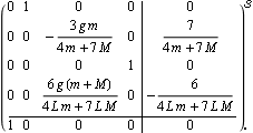
You can also obtain the generic solution to a state-feedback design for a set of closed-loop poles at {p1, p2, ..., pk}. This is the state-space model of an inverted pendulum system from Section 9.2 of Control System Professional. | Out[26]= |  |
This defines the desired closed-loop poles for the inverted pendulum system. These are the generic state-feedback gains for this pole set, using the mapping algorithm | Out[30]= |  |
This is the resulting compensator for a particular set of numerical values of the system parameters and the desired poles. | Out[32]= |  |
This is the inverted pendulum system with the numerical values of the system parameters. | Out[34]= |  |
These are the resulting closed-loop system poles. | Out[36]= |  |
|