Automotive Muffler Simulation
Introduction
As a car engine runs, a significant amount of noise is generated due to the combustion. An automotive muffler is an essential device that attenuates the noise exhaustion from the engine.
This study simulates the sound propagation within three different kinds of mufflers and compares their performances, varying from the frequency ![]() to
to ![]() . The mufflers analyzed here are a classical muffler, a perforated muffler and a padded muffler. The sound pressure distribution and the transmission loss spectrum will be calculated to show the damping behavior of these types of mufflers.
. The mufflers analyzed here are a classical muffler, a perforated muffler and a padded muffler. The sound pressure distribution and the transmission loss spectrum will be calculated to show the damping behavior of these types of mufflers.
The symbols and corresponding units used throughout this tutorial are summarized in the Nomenclature section.
Please refer to the information provided in "Acoustics in the Frequency Domain" for more general theoretical background for acoustics.
Needs["NDSolve`FEM`"]
$HistoryLength = 0;
Frequency Domain Acoustic Model
To study the performance of a muffler over a range of frequencies, an acoustic model is built in the frequency domain based on the source-free Helmholtz partial differential equation (PDE):
vars = {p[x, y, z], ω, {x, y, z}};
AcousticPDEComponent[vars, <|"SoundSpeed" -> c, "MassDensity" -> ρ|>]Subscript[c, air] = QuantityMagnitude[ThermodynamicData["Air", "SoundSpeed"]];
Subscript[ρ, air] = QuantityMagnitude[ThermodynamicData["Air", "Density"]];pars = <|"SoundSpeed" -> Subscript[c, air], "MassDensity" -> Subscript[ρ, air]|>;Domain
The classical acoustic muffler consists of three parts: an inlet pipe, an outlet pipe and expansion chambers. Note that the inlet and outlet pipes are assumed to have infinite extension and are modeled with a radiation boundary condition and an absorbing boundary condition, respectively.
There are two common ways to further improve the muffler performance. The first method is to use perforated pipes within the muffler, and the second method is to cover the walls of the muffler with sound-absorbing pads. Each technique has its advantages and disadvantages, and will be explained in a later section.
L = 1;
r1 = 0.05;
r2 = 0.03;
l = 0.2;
inlet = -l;
outlet = L + l;
pipeArea = π r1^2;
Boundary Conditions
There are three types of boundary conditions involved in this example. To model the incoming sound wave at the inlet, a radiation boundary condition is used.
This radiation boundary condition is very general. However, in the 3D case, it may use up more memory than is available. To reduce the memory requirement, observe that the inlet is at ![]() . Therefore, the boundary normal is in the direction
. Therefore, the boundary normal is in the direction ![]() . This boundary unit normal can be specified as a parameter and will simplify the boundary condition.
. This boundary unit normal can be specified as a parameter and will simplify the boundary condition.
pIn = 1;
Subscript[Γ, RBC] = AcousticRadiationValue[z ≤ inlet, vars, pars, <|"SoundIncidentPressure" -> pIn, "BoundaryUnitNormal" -> {0, 0, -1}|>]
To model the outgoing wave at the outlet, an absorbing boundary condition is specified.
Subscript[Γ, ABC] = AcousticAbsorbingValue[z ≥ outlet, vars, pars]On the remaining walls of the muffler, the default sound hard boundary conditions are used. Since the sound hard boundary condition is the default boundary condition, nothing needs to be further specified.
Model 1: Classical Muffler
To obtain a benchmark case, consider a classical muffler without any perforation or sound absorbing pads.
bmesh1 = ToBoundaryMesh@Import[FileNameJoin[...]];
bmesh1["Wireframe"]
In acoustics simulations, the wavelength ![]() of a sound wave needs to be resolved by a sufficiently fine mesh in order to get an accurate numerical solution. Here the max edge length is set to 12 nodes per
of a sound wave needs to be resolved by a sufficiently fine mesh in order to get an accurate numerical solution. Here the max edge length is set to 12 nodes per ![]() , which means that there will be at least 12 elements per wavelength
, which means that there will be at least 12 elements per wavelength ![]() in each direction of the wave propagation.
in each direction of the wave propagation.
λ = (c / Subscript[f, max]) /. {c -> Subscript[c, air], Subscript[f, max] -> 1000};
h = λ / 12;mesh1 = ToElementMesh[bmesh1, MaxCellMeasure -> {"Length" -> h}]pde1 = AcousticPDEComponent[vars, pars] == Subscript[Γ, RBC] + Subscript[Γ, ABC];To study the behavior of the muffler over the frequency range ![]() , the PDE model is solved repetitively with ParametricNDSolveValue.
, the PDE model is solved repetitively with ParametricNDSolveValue.
fRange = Table[f, {f, 20, 1000, 10}];
pfun1 = ParametricNDSolveValue[pde1, p, {x, y, z}∈mesh1, {ω}];
Monitor[pfunTable1 = Table[pfun1[ω] /.  {ω -> 2 π f}, {f, fRange}], Row[...]];
Model 2: Muffler with Perforation
The next case considers a muffler with perforation. The perforated pipes allow the sound pressure wave to scatter out in various directions within the expansion chamber.
bmesh2 = ToBoundaryMesh@Import[FileNameJoin[...]];
bmesh2["Wireframe"]mesh2 = ToElementMesh[bmesh2, MaxCellMeasure -> {"Length" -> h}]In this scenario, the PDE is the same as in the previous case.
pde2 = AcousticPDEComponent[vars, pars] == Subscript[Γ, RBC] + Subscript[Γ, ABC];Note that running the following simulation will require hardware that has more than 8GB of memory.
MemoryAvailable[] / 1024. ^ 2fRange = Table[f, {f, 20, 1000, 10}];
pfun2 = ParametricNDSolveValue[pde2, p, {x, y, z}∈mesh2, {ω}];
Monitor[pfunTable2 = Table[pfun2[ω] /. {ω -> 2π f}, {f, fRange}], Row[...]];Model 3: Muffler with Sound-Absorbing Pads
The last scenario considers a muffler with sound-absorbing materials padded on the inner walls. Common sound-absorbing materials are made of fiberglass or steel wool. Depending on the density and the mean radius of the material [1], the flow resistivity ![]() values typically lie in the range of
values typically lie in the range of ![]() to
to ![]() .
.
In the following model, a fiberglass pad with flow resistivity ![]() and thickness
and thickness ![]() is used.
is used.
Subscript[R, f] = 50000;
n = 0.02;
A technique to model the sound propagation within absorptive materials is called the "equivalent fluid method" [2]. The idea is to characterize the sound attenuation by inserting the effective density ![]() and the effective speed of sound
and the effective speed of sound ![]() in the original Helmholtz equation (3).
in the original Helmholtz equation (3). ![]() and
and ![]() are complex valued and can be calculated with an empirical formula derived by Delany and Bazley [4]. For the low-frequency range where the non-dimensional parameter
are complex valued and can be calculated with an empirical formula derived by Delany and Bazley [4]. For the low-frequency range where the non-dimensional parameter ![]() , Kirby and Cummings [5] presented the following, more accurate approximations:
, Kirby and Cummings [5] presented the following, more accurate approximations:
Here ![]() and
and ![]() are the complex wave number and complex impedance, respectively.
are the complex wave number and complex impedance, respectively.
{Subscript[ψ, min], Subscript[ψ, max]} = (ρ #/Subscript[R, f])& /@ {Subscript[f, min], Subscript[f, max]} /. {ρ -> Subscript[ρ, air], Subscript[f, min] -> 100, Subscript[f, max] -> 1000}Since the parameter ![]() over the entire spectrum, the equation (6) should be used to calculate the complex parameters
over the entire spectrum, the equation (6) should be used to calculate the complex parameters ![]() and
and ![]() .
.
Subscript[k, c] = k * (1 + 0.136 * ((ρ ω/2π Subscript[R, f]))^-0.641 - 0.322 I * ((ρ ω/2π Subscript[R, f]))^-0.502) /. {k -> (ω/Subscript[c, air]), ρ -> Subscript[ρ, air]};
Subscript[Z, c] = Z * (1 + 0.081 * ((ρ ω/2π Subscript[R, f]))^-0.699 - 0.191 I * ((ρ ω/2π Subscript[R, f]))^-0.556) /. {Z -> Subscript[ρ, air] * Subscript[c, air], ρ -> Subscript[ρ, air]};
Subscript[c, c] = ω / Subscript[k, c];
Subscript[ρ, c] = Subscript[k, c] * Subscript[Z, c] / ω;MaterialRules = With[{cc = Subscript[c, c], ρc = Subscript[ρ, c], cair = Subscript[c, air], ρair = Subscript[ρ, air]}, {c -> If[(x^2/(0.25 - n)^2) + (y^2/(0.1 - n)^2) ≥ 1, cc, cair],
ρ -> If[(x^2/(0.25 - n)^2) + (y^2/(0.1 - n)^2) ≥ 1, ρc, ρair]}];pde3 = AcousticPDEComponent[vars, <|"SoundSpeed" -> c, "MassDensity" -> ρ, MaterialRules|>] == Subscript[Γ, RBC] + Subscript[Γ, ABC];fRange = Table[f, {f, 20, 1000, 10}];
pfun3 = ParametricNDSolveValue[pde3, p, {x, y, z}∈mesh1, {ω}];
Monitor[pfunTable3 = Table[pfun3[ω] /. {ω -> 2π f}, {f, fRange}], Row[...]];Post-processing and Visualization
Sound Pressure Distribution
To see the general damping behavior of acoustic waves, the sound propagation is visualized within the classical muffler. The harmonic wave relation (7) is applied to transform the solution into the time domain:
f = 600;
{index} = Flatten[Position[fRange, f]];
pMax = Max[Abs[#[[index]]["ValuesOnGrid"]]& /@ {pfunTable1, pfunTable2, pfunTable3}]legendBar = BarLegend[{"TemperatureMap", {-pMax, pMax}}, ...];
options = {PlotRange -> {-pMax, pMax}, ...};nframes = 30;
frames = Table[Labeled[Legended[SliceContourPlot3D[Re[pfunTable1[[index]][x, y, z] * Exp[I ω t] /. {ω -> 2π f}], {x, y, z}∈mesh1, Evaluate[options]], legendBar], ...], {t, 0, 0.002, 0.002 / nframes}];
frames = Rasterize[#1, "Image", ImageSize -> 550, RasterSize -> 550]& /@ frames;
ListAnimate[...]See this note about improving the visual quality of the animation.
Within the inlet pipe and the first expansion chamber, the sound wave appears to be fixed in space, but it simply oscillates in time. This type of wave is known as a standing wave, and often forms several local extrema of the sound pressure.
This excess sound pressure is called "back-pressure" [8], which will restrict the gas flow within the muffler and reduce the power output of the car engine. To see how the perforated and padded mufflers improve this issue, it is better to visualize the amplitude distribution ![]() of the sound pressure waves.
of the sound pressure waves.
{P1, P2, P3} = Rasterize[#1, "Image", ImageSize -> 550, RasterSize -> 550]& /@ {...};
Manipulate[Labeled[Which[Type == "Classical", P1, Type == "Perforated", P2, Type == "Padded", P3], ...], ...]
Both the perforated and padded mufflers improve the effect of back-pressure that is seen in the classical muffler. Because the sound pressure wave is allowed to dissipate within the muffler pipes, the perforated muffler created the lowest back-pressure among the three cases.
To further investigate these results at different frequencies, the index of the solution data pfunTable can be altered.
Transmission Loss
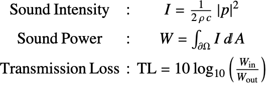
Another important quantity to measure the performance of an acoustic muffler is the transmission loss (TL), which is defined as the ratio between the incident and the transmitted sound power. The formulas for the transmission loss, sound power and sound intensity are given by:
Iin = pIn^2 / (2Subscript[ρ, air] Subscript[c, air]);
Win = Iin * pipeArea;{Iout1, Iout2, Iout3} =
Table[(Abs[#[[i]][x, y, z]]^2 / (2Subscript[ρ, air] Subscript[c, air])) /. {x -> 0.15, y -> 0, z -> outlet}, {i, fRange//Length}]& /@ {pfunTable1, pfunTable2, pfunTable3};
{Wout1, Wout2, Wout3} = # * pipeArea& /@ {Iout1, Iout2, Iout3};{TL1, TL2, TL3} = 10 * Log[10, Win / #]& /@ {Wout1, Wout2, Wout3};
ListLinePlot[{Transpose[{fRange, TL1}], Transpose[{fRange, TL2}], Transpose[{fRange, TL3}]}, ...]For the classical muffler, the transmission loss curve appears in a wavelike pattern with few dips. These dips correspond to the resonance frequencies of the muffler, where the sound transmission is enhanced and the muffler becomes less effective. The padded muffler, however, not only smooths out these dips but also increases the overall transmission loss values, especially for the higher frequencies, making it a more effective muffler in that range. Note that although the perforated muffler has the best effect on the back-pressure issue, it has generally smaller transmission loss values over the spectrum except for the frequency around ![]() .
.
More advanced mufflers can be constructed by combining the features of absorptive pads and perforation [9]. If there is a targeting frequency range where the noise is to be controlled, the dimension of each expansion chamber can also be customized to meet the functional requirements.
Unmuffled versus Muffled Engine Noise
To hear the damping effect of the acoustic muffler, an audio file of unmuffled engine noise is used as the sound input.
pInTD = AudioData[Audio[File[...]]][[1]];
audio = Audio[pInTD]n = Length@pInTD;
rs = QuantityMagnitude[AudioSampleRate[audio]];In order to process the sound signal, a Fourier transform is used to convert the input noise from the time domain to the frequency domain.
pInFD = Fourier[pInTD, FourierParameters -> {-1, 1}];As explained in a separate tutorial, the discrete Fourier transform generates ![]() Fourier coefficients
Fourier coefficients ![]() with the symmetric property that
with the symmetric property that ![]() . For each pair of the Fourier coefficients
. For each pair of the Fourier coefficients ![]() and
and ![]() , the corresponding frequency component is
, the corresponding frequency component is ![]() .
.
df = rs / n;
fcomp = Table[f, {f, 0, rs - df, df}];
Each frequency component is then processed by the frequency response function, which is defined as the ratio between the input and the output sound amplitude: ![]() .
.
temp = Table[(Abs[#[[i]][x, y, z]] / Abs[pIn]) /. {x -> 0.15, y -> 0, z -> outlet}, {i, fRange//Length}]& /@ {pfunTable1, pfunTable2, pfunTable3};
{H1, H2, H3} = Interpolation[Transpose[{fRange, #}]]& /@ temp;{imin, imax} = Flatten[Position[fcomp, #]& /@ MinMax@fRange];Damping[FRfun_, pInFD_] := Module[{H, pOutFD},
H = FRfun;
pOutFD = pInFD;
For[i = imin, i ≤ imax, i++,
pOutFD[[i]] = pOutFD[[i]] * H[(i - 1) * rs / n];
pOutFD[[n - i + 2]] = pOutFD[[n - i + 2]] * H[(i - 1) * rs / n]];
pOutFD]pOutFD = Damping[#, pInFD]& /@ {H1, H2, H3};pOutTD = Sqrt[n] * InverseFourier[#]& /@ pOutFD;
AudioOut = Audio[Re[#]]& /@ pOutTD;
Manipulate[Which[...], {...}, Rule[...]]spectrum = Transpose[{fcomp, 2Abs@#}]& /@ Join[{pInFD}, pOutFD];
ListLinePlot[spectrum, ...]Based on the output audio and the amplitude spectrum, the engine noise has been significantly damped by all of the mufflers. For the low-frequency range ![]() , of which the noise is mostly composed, the padded muffler shows the best sound attenuation.
, of which the noise is mostly composed, the padded muffler shows the best sound attenuation.
Nomenclature
| Symbol | Description | Unit |
| ρ | density | [kg/m3] |
| c | speed of sound | [m/s] |
| p | sound pressure | [Pa] |
| p | sound amplitude | [Pa] |
| ω | sound wave angular frequency | [rad/s] |
| f | sound wave frequency | [Hz] |
| X | position vector | [m] |
| R | radius of the expansion chamber | [m] |
| L | length of the expansion chamber | [m] |
| r | radius of the inlet/outlet pipe | [m] |
| l | length of the inlet/outlet pipe | [m] |
| Rf | flow resistivity | [N·s/m3] |
| λ | eigenvalue | [rad2·m/kg] |
| TL | transmission loss | N/A |
| W | sound power | [W] |
| I | sound intensity | [W/m2] |
References
1. D. PotenteD. "General Design Principles for an Automotive Muffler," in Proceedings of ACOUSTICS 2005, 2005 pp. 153–158.
2. R. Kirby and A. Cummings. "Prediction of the bulk acoustic properties of fibrous materials at low frequencies", in Applied Acoustics, Volume 56, Issue 2, February 1999, Pages 101-125, https://doi.org/10.1016/S0003-682X(98)00015-2
3. M. E. Delany and E. N. Bazley. "Acoustical Properties of Fibrous Absorbent Materials." Applied Acoustics 3(2), 1970 pp. 105–116.
4. F. Fahy. Foundations of Engineering Acoustics. Cambridge, MA: Academic Press. 2001.
5. T. J. Cox and P. D'Antonio. Acoustic Absorbers and Diffusers: Theory, Design, and Application. London: Spon Press. 2004.