Wave Diffraction and Interference Simulation
| Introduction | Single-Slit Model |
| Pressure Acoustics Model | Double-Slit Model |
| Domain | Nomenclature |
| Boundary Conditions | References |
| Model Parameters Setup |
Introduction
When a wave encounters an obstacle or a slit, some portion of the incident wave is reflected while the remaining part is transmitted in a distorted shape. The effect is generally more prominent for waves whose wavelength is roughly comparable to the dimensions of the diffracting object.
The following 2D model simulates the classic single- and double-slit experiments for acoustic waves. Sinusoidal plane waves are set to enter the domain from the bottom of the domain. By inspecting the wave propagation, one can clearly see the effect of wave diffraction and interference.
The symbols and corresponding units used throughout this tutorial are summarized in the Nomenclature section.
Please refer to the information provided in "Acoustics in the Frequency Domain" for more general theoretical background for acoustics.
Needs["NDSolve`FEM`"]Pressure Acoustics Model
The propagation of harmonic sound waves can be described by the source-free Helmholtz partial differential equation (PDE) (1):
vars = {p[x, y], ω, {x, y}};
AcousticPDEComponent[vars, <|"SoundSpeed" -> c, "MassDensity" -> ρ|>]Subscript[c, air] = QuantityMagnitude[ThermodynamicData["Air", "SoundSpeed"]];
Subscript[ρ, air] = QuantityMagnitude[ThermodynamicData["Air", "Density"]];pars = <|"SoundSpeed" -> Subscript[c, air], "MassDensity" -> Subscript[ρ, air]|>;Domain
First, geometric models for the single- and double-slit experiments are constructed. The width of each slit is set to ![]() , and the separation distance for the double-slit model is defined as
, and the separation distance for the double-slit model is defined as ![]() . A time-harmonic sound wave enters the domain from the lower boundary
. A time-harmonic sound wave enters the domain from the lower boundary ![]() and leaves from the semicircle boundary
and leaves from the semicircle boundary ![]() . The wall boundary is represented by
. The wall boundary is represented by ![]() .
.
When the incident wave reaches the slit, diffraction occurs and makes each slit behave as if it were a point monopole sound source. For the double-slit case, two diffraction waves will then superimpose with each other and form an interference pattern.
bottom = 0;
R = 0.6;
L = 0.25;
ws = 0.03;
d = 0.2;
w = 0.01;Ωsingle =
RegionUnion[Disk[{0, L}, R, {0, π}], Rectangle[{-R, bottom}, {R, L - w}],
Rectangle[{-ws / 2, L - w}, {ws / 2, L}]];Ωdouble =
RegionUnion[Disk[{0, L}, R, {0, π}], Rectangle[{-R, bottom}, {R, L - w}],
Rectangle[{-d / 2 - ws / 2, L - w}, {-d / 2 + ws / 2, L}], Rectangle[{d / 2 - ws / 2, L - w}, {d / 2 + ws / 2, L}]];Boundary Conditions
There are three types of boundary conditions involved in this example. On the lower boundary ![]() , a radiation boundary condition is used to model the incoming sound wave.
, a radiation boundary condition is used to model the incoming sound wave.
pIn = 5;
Subscript[Γ, in] = AcousticRadiationValue[y == bottom, vars, pars, <|"SoundIncidentPressure" -> pIn|>];
On the semicircle boundary ![]() , an absorbing boundary condition is specified to model the outgoing wave.
, an absorbing boundary condition is specified to model the outgoing wave.
Subscript[Γ, out] = AcousticAbsorbingValue[y ≥ L - w, vars, pars];For the remaining boundaries, a default sound hard boundary condition is implicitly used.
Model Parameters Setup
Since the diffraction pattern is more prominent for a wave whose wavelength is comparable to the size of the diffracting object, a wavelength ![]() is used.
is used.
λ = 0.1;
f = Subscript[c, air] / λ;
In acoustics simulations, the wavelength ![]() of a sound wave needs to be resolved by a sufficiently fine mesh in order to get an accurate numerical solution. Here the max edge length is set to 12 nodes per
of a sound wave needs to be resolved by a sufficiently fine mesh in order to get an accurate numerical solution. Here the max edge length is set to 12 nodes per ![]() , which means that there will be at least 12 elements per wavelength
, which means that there will be at least 12 elements per wavelength ![]() in each direction of the wave propagation.
in each direction of the wave propagation.
h = λ / 12;Single-Slit Model
First, consider the single-slit case in order to study the diffraction pattern of the sound wave. The PDE model is solved numerically with NDSolveValue, using the finite element method.
pde = AcousticPDEComponent[vars, pars] == Subscript[Γ, in] + Subscript[Γ, out] /. ω -> 2π f;pfunSingle = NDSolveValue[pde, p, {x, y}∈Ωsingle, Method -> {"PDEDiscretization" -> {"FiniteElement", "MeshOptions" -> {"MaxCellMeasure" -> {"Length" -> h}}}}];To visualize the sound diffraction pattern from the single slit, the solution needs to be transformed into the time domain with the harmonic wave relation (2):
More information on the relation between time domain and frequency domain can be found here.
pMax = Max[Abs[pfunSingle["ValuesOnGrid"]]];
options = {PlotRange -> {-pMax, pMax}, ...};boundaryHighlight = Graphics[{...}];
nframes = 50;
Monitor[frames = Table[
Show[ContourPlot[Evaluate[Re[pfunSingle[x, y] * Exp[I ω t] /. {ω -> 2π f}]], {x, y}∈Ωsingle, ...], boundaryHighlight], {t, 0, 0.001, 0.001 / nframes}];, "time: " <> ToString[t]];
frames = Rasterize[#1, "Image", ImageResolution -> 80]& /@ frames;
ListAnimate[frames, Rule[...]]See this note about improving the visual quality of the animation.
The diffraction effect is seen once the incident wave passes the slit. The wave is then deformed from a plane wave to a circular wave that propagates toward the semicircle boundary. The slit behaves as if it were a point monopole sound source.
Double-Slit Model
Next, the double-slit model is solved to show the interference effect between two diffraction sound waves.
pfunDouble = NDSolveValue[pde, p, {x, y}∈Ωdouble, Method -> {"PDEDiscretization" -> {"FiniteElement", "MeshOptions" -> {"MaxCellMeasure" -> {"Length" -> h}}}}];boundaryHighlight = Graphics[{...}];
nframes = 50;
Monitor[frames = Table[Show[ContourPlot[Evaluate[Re[pfunDouble[x, y] * Exp[I ω t] /. {ω -> 2π f}]], {x, y}∈Ωdouble, ...], boundaryHighlight], {t, 0, 0.001, 0.001 / nframes}];, "time: " <> ToString[t]];
frames = Rasterize[#1, "Image", ImageResolution -> 80]& /@ frames;
ListAnimate[...]See this note about improving the visual quality of the animation.
In the double-slit case, the two diffraction waves superimpose with each other and form an interference pattern. To verify the numerical result, the theoretical values for the directions of the maximal and minimal amplitudes [3] can be calculated. Note that the constructive interference occurs when two waves are in phase—that is, the path difference between them equals an integral number of the wavelength. On the contrary, the destructive interference occurs when the path difference is an odd multiple of half of the wavelength.
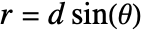
The path difference ![]() between two waves traveling at an angle
between two waves traveling at an angle ![]() is:
is:
The maximal and minimal sound amplitudes occur when:
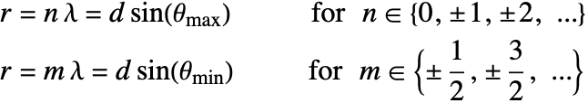
anglesMax = Table[ArcSin[n λ / d], {n, {-1, 0, 1}}]anglesMin = Table[ArcSin[n λ / d], {n, {-3 / 2, -1 / 2, 1 / 2, 3 / 2}}]refLine = Line[{{0, L}, {0, L + R}}];Show[ContourPlot[Re[pfunDouble[x, y]], {x, y}∈Ωdouble, ..., Epilog -> {{Dashed, Red, Table[Rotate[refLine, θ, {0, L}], {θ, anglesMax}]}, {Dashed, Blue, Table[Rotate[refLine, θ, {0, L}], {θ, anglesMin}]}, {...}}], boundaryHighlight]The theoretical prediction matches the result from NDSolve.
To inspect the sound difference within the domain, the sound pressure values are extracted from an arbitrary trajectory (green line), which passes through the amplitude extrema. An audio file is then generated and captures a sound as if traversing along this trajectory within the domain.
pValues[trajectory_] := Function[t, Re[pfunDouble@@trajectory[t] * Exp[I ω t] /. {ω -> 2π f}]]Subscript[θ, start] = π / 3;
Subscript[θ, end] = 2π / 3;
greenTrajectory[t_] := {0.3Cos[θ], 0.3Sin[θ] + L} /. {θ -> Subscript[θ, start] + t * (Subscript[θ, end] - Subscript[θ, start]) / 2}AudioGenerator[pValues[greenTrajectory], 2]//AudioNormalizeNote that the sound varies with time while traversing along the trajectory, and the change in volume corresponds to the sound diffraction pattern within the domain.
Nomenclature
| Symbol | Description | Unit |
| ρ | density of a medium | [kg/m3] |
| c | speed of sound in a medium | [m/s] |
| p | sound pressure | [Pa] |
| ω | sound wave angular frequency | [rad/s] |
| f | sound wave frequency | [Hz] |
| λ | sound wavelength | [m] |
| t | time | [s] |
| X | position vector | [m] |
| L | length of the plane wave domain | [m] |
| ws | width of the slit | [m] |
| w | depth of the slit | [m] |
| R | radius of the outer boundary | [m] |
| d | slit separation | [m] |
| n | arbitrary integer | N/A |
| θ | wave traveling angle | [rad] |
| Γin | inlet boundary | N/A |
| Γout | outer boundary | N/A |
| Ω | computational domain | N/A |
References
1. F. Fahy. Foundations of Engineering Acoustics. Cambridge, MA: Academic Press. 2001.
2. A. Norton. Dynamic Fields and Waves of Physics. Boca Raton: CRC Press. 2000.