Heat Exchanger
Introduction
A heat exchanger is a device that aims to transfer thermal energy between two or more media. In this example, a series of hot wires is submerged in a flow field to serve as a heat source. Cold water enters the domain from the bottom, flows across the heated wires, withdraws heat and then exits heated through the top:

The following simulation models the temperature, pressure and velocity fields within the heat exchanger, showing the effect of natural convection. The mean temperature of the outgoing flow is then calculated to measure the effectivity of the heat exchanger.
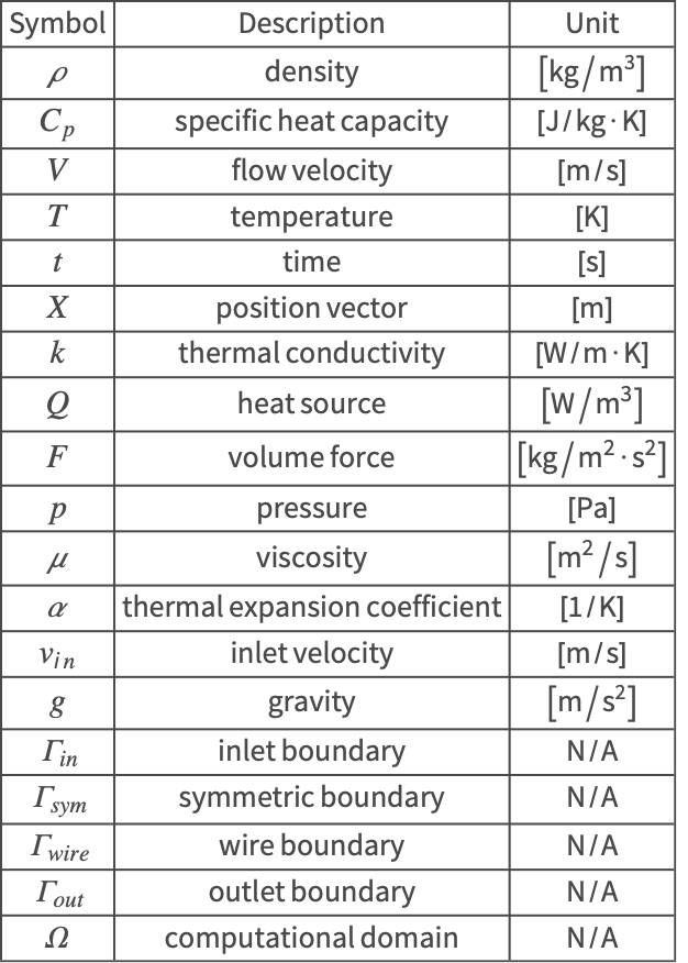
The symbols and corresponding units used here are summarized in the Nomenclature section.
Please refer to the information provided in "Heat Transfer" for a more general theoretical background for heat transfer analysis.
Needs["NDSolve`FEM`"]Multiphysics Model
Since this problem considers more than one physics domain, a multiphysics model is constructed. The heat equation is coupled to the Navier–Stokes equation for modeling heat transfer through the fluid flow.
Heat Transfer Model
The heat equation (1) is used to solve for the temperature field in a heat transfer model:
For a steady-state heat transfer model without sources, the transient term ![]() and the source term
and the source term ![]() in (2) are set to zero and the heat equation simplifies to:
in (2) are set to zero and the heat equation simplifies to:
Note that the heat convected by the fluid flow is modeled by the convective term. As such, the fluid flow velocity field ![]() is the input of the convective term
is the input of the convective term ![]() in the heat equation.
in the heat equation.
tvars = {T[x, y], {x, y}};
pars = <|"MassDensity" -> ρ, "SpecificHeatCapacity" -> Cp, "ThermalConductivity" -> k * IdentityMatrix[2], "HeatConvectionVelocity" -> {u[x, y], v[x, y]}|>;
SteadyHeatModel = HeatTransferPDEComponent[tvars, pars]
Fluid Dynamics Model
The Navier–Stokes equation (3) is used to describe the steady-state laminar flow field within the heat exchanger. As the fluid near the wires absorbs heat, it becomes less dense and rises due to thermal expansion. This temperature-induced buoyancy force ![]() serves as an extra driving force of the flow besides the inflow velocity and appears as the source term on the right-hand side of (4):
serves as an extra driving force of the flow besides the inflow velocity and appears as the source term on the right-hand side of (4):
The magnitude of this buoyancy force ![]() is equivalent to weight of the displaced fluid, that is, the fluid density
is equivalent to weight of the displaced fluid, that is, the fluid density ![]() times its volume change
times its volume change ![]() and the standard gravity
and the standard gravity ![]() . This is also known as the Boussinesq approximation [5]:
. This is also known as the Boussinesq approximation [5]:
![]() is the density
is the density ![]() ,
,![]() is the gravity
is the gravity ![]() ,
,![]() is the viscosity
is the viscosity ![]() ,
,![]() is the thermal expansion coefficient
is the thermal expansion coefficient ![]() ,
,![]() is the pressure
is the pressure ![]() ,
,![]() is the inflow temperature
is the inflow temperature ![]() .
.
pars["DynamicViscosity"] = μ;
CFDvars = {{u[x, y], v[x, y], p[x, y]}, {x, y}};
CFDModel = FluidFlowPDEComponent[CFDvars, pars]
{Subscript[F, x], Subscript[F, y]} = {0, α * g * ρ * (T[x, y] - Subscript[T, in])};Subscript[ρ, water] = QuantityMagnitude[ThermodynamicData["Water", "Density"]];
Subscript[k, water] = QuantityMagnitude[ThermodynamicData["Water", "ThermalConductivity"]];
Subscript[μ, water] = QuantityMagnitude[ThermodynamicData["Water", "Viscosity"]];
Subscript[Cp, water] = QuantityMagnitude[ThermodynamicData["Water", "IsobaricHeatCapacity"]];Domain
The heat exchanger model consists of two series of heated wires that are submerged in the flow field. By assuming that the heated pipes are infinitely long, the temperature variation in the ![]() direction can be neglected. Therefore a two-dimensional model is sufficient.
direction can be neglected. Therefore a two-dimensional model is sufficient.
Due to the symmetry along the ![]() axis, it is efficient to construct the simulation domain
axis, it is efficient to construct the simulation domain ![]() with only the right half between the heated wires, where
with only the right half between the heated wires, where ![]() and
and ![]() denote the inlet and outlet boundary. The wire boundary and the symmetric boundary are symbolized as
denote the inlet and outlet boundary. The wire boundary and the symmetric boundary are symbolized as ![]() and
and ![]() , respectively:
, respectively:

w = 0.005;
h = 0.045;
r = 0.0025;Ω = RegionDifference[Rectangle[{0, 0}, {w, h}], RegionUnion[Disk[{0, 0.015}, r], Disk[{0, 0.03}, r]]];In order to get a good result, a grid finer than the default is used for the mesh generation. Here the maximum grid size is set to ![]() , which means that there will be about 10 elements in the
, which means that there will be about 10 elements in the ![]() direction (width) and 100 elements in the
direction (width) and 100 elements in the ![]() direction (length). Exact arithmetic is used for the input. This helps to find very accurate region bounds.
direction (length). Exact arithmetic is used for the input. This helps to find very accurate region bounds.
mesh = ToElementMesh[Ω, "MaxCellMeasure" -> 10 ^ -7]Boundary Conditions
This multiphysics simulation contains both a heat transfer model and a fluid dynamics model and boundary conditions for each physics mode need to be set up.
Heat Transfer Model
There are three types of boundary conditions involved in the heat transfer model. At the flow inlet ![]() and the wire boundaries
and the wire boundaries ![]() , the temperatures are set to
, the temperatures are set to ![]() and
and ![]() .
.
wire1 = x^2 + (y - 0.015)^2 ≤ r^2;
wire2 = x^2 + (y - 0.03)^2 ≤ r^2;
Subscript[Γ, temp] =
	{HeatTemperatureCondition[y == 0, tvars, pars, <|"SurfaceTemperature" -> Subscript[T, in]|>], HeatTemperatureCondition[wire1 || wire2, tvars, pars, <|"SurfaceTemperature" -> Subscript[T, wire]|>]};
Since the outflow boundary condition and the symmetric boundary condition are both Neumann zero conditions, they are implicitly applied on the flow outlet ![]() and the symmetric boundary
and the symmetric boundary ![]() .
.
Fluid Dynamics Model
There are four types of the boundary conditions involved in the fluid dynamics model. At the inlet ![]() , the flow velocity is set to
, the flow velocity is set to ![]() .
.
Subscript[Γ, inlet] = DirichletCondition[{u[x, y] == 0, v[x, y] == Subscript[v, in]}, y == 0];At the boundary of the heated wires, the flow velocity is set to zero to model a no-slip fluid flow.
Subscript[Γ, wall] = DirichletCondition[{u[x, y] == 0, v[x, y] == 0}, wire1 || wire2];At the top boundary, a pressure outlet boundary condition is used to model the outgoing flow. Here the outlet pressure is set equal to the ambient pressure ![]() .
.
Subscript[Γ, outlet] = DirichletCondition[p[x, y] == 0, y == h];Due to the symmetry at the ![]() axis, the velocity in the
axis, the velocity in the ![]() direction is set to zero at the symmetry boundaries
direction is set to zero at the symmetry boundaries ![]() .
.
Subscript[Γ, sym] = DirichletCondition[u[x, y] == 0, x == 0 || x == w];bcs = {Subscript[Γ, wall], Subscript[Γ, inlet], Subscript[Γ, outlet], Subscript[Γ, sym], Subscript[Γ, temp]};Solve the PDE Model
The thermal expansion coefficient ![]() , the inlet velocity
, the inlet velocity ![]() and the standard gravity
and the standard gravity ![]() are given by:
are given by:

The temperatures of the inflow and heated wires are held at ![]() and
and ![]() , respectively.
, respectively.
parameters =
{ρ -> Subscript[ρ, water], k -> Subscript[k, water], μ -> Subscript[μ, water], Cp -> Subscript[Cp, water], α -> 1.8 * 10^-4, g -> 9.81, Subscript[T, in] -> 300, Subscript[T, wire] -> 375};pde = {CFDModel == {Subscript[F, x], Subscript[F, y], 0}, SteadyHeatModel == 0, bcs} /. parameters;A stable solution can be found if the velocities are interpolated with a higher order than the pressure. NDSolve allows an interpolation order for each dependent variable to be specified. Here the velocities ![]() and
and ![]() and the temperature
and the temperature ![]() are set to be interpolated with second order and the pressure
are set to be interpolated with second order and the pressure ![]() with first order.
with first order.
To solve this strongly nonlinear PDE it is best to increase the nonlinearity step by step. For this a parametric function in the inflow velocity ![]() is created. The process is explained in detail in the Laminar Flow monograph.
is created. The process is explained in detail in the Laminar Flow monograph.
pfun = ParametricNDSolveValue[pde, {u, v, p, T}, Element[{x, y}, mesh], Subscript[v, in], Method -> {"PDEDiscretization" -> {"FiniteElement", "InterpolationOrder" -> {u -> 2, v -> 2, p -> 1, T -> 2}}}]In the initial step a very low inflow velocity is used. The solution to this slow inflow is then used as an initial seed for an inflow that is a bit higher. The process is repeated until the inflow velocity reaches a value of ![]() . The initial seed is set to zero.
. The initial seed is set to zero.
uFun = 0&;
vFun = 0&;
pFun = 0&;
tFun = 0&;
Do[
	PrintTemporary["Current inflow velocity: ", N[inflowVelocity]];
	{uFun, vFun, pFun, tFun} = pfun[inflowVelocity, "InitialSeeding" -> {u[x, y] == uFun[x, y], v[x, y] == vFun[x, y], p[x, y] == pFun[x, y], T[x, y] == tFun[x, y]}]
	, {inflowVelocity, 1 / {20000, 2000, 1500, 1000, 700, 500, 200}}]
In the following sections, compare the temperature and flow field under different inflow velocities ![]() and wire temperatures
and wire temperatures ![]() . The current result is saved for later use.
. The current result is saved for later use.
{uSlow, vSlow, pSlow, TSlow} = {uFun, vFun, pFun, tFun};Post-processing and Visualization
To inspect the heat transfer due to the fluid flow, the following visualization combines the resulting velocity field with the temperature distribution.
TRange = MinMax[TSlow["ValuesOnGrid"]];
legendBar = BarLegend[{"TemperatureMap", TRange}, 50, ...];
options = {...};boundaryHighlight = Graphics[...];
g1 = Show[VectorPlot[{uSlow[x, y], vSlow[x, y]}, {x, y}∈mesh, ...], boundaryHighlight];
g2 = Show[ContourPlot[TSlow[x, y], {x, y}∈mesh, Evaluate[options]], boundaryHighlight];
lis = {g1, g2};
lis = Rasterize[#1, ImageResolution -> 300]& /@ lis;
GraphicsRow[lis, ImageSize -> 350, Spacings -> {100, 0}]The temperature visualization above has a dashed region. This region will be enlarged in the next visualization.
Show[Legended[...], VectorPlot[{uSlow[x, y], vSlow[x, y]}, {x, y}∈mesh, PlotTheme -> "Scientific"]]See this note about improving the visual quality of the plot.
The increased temperature around the wire results in a greater buoyancy force that speeds up the flow behind the wire. If the wire is unheated (as shown in the later section: Flow Field around Unheated Wires), the water will flow slower behind the wire.
To measure the effectivity of the heat exchanger, the mean temperature rise is calculated between the flow inlet ![]() and outlet
and outlet ![]() :
:
Subscript[T, out] = NIntegrate[TSlow[x, h], {x, 0, w}] / wWith the heat exchanger, the temperature of the flow has risen by about ![]() .
.
To inspect the heat exchanger under different flow conditions, the model can be reused conveniently by tweaking the model parameters. The procedure is shown in the section: Heat Exchanger with Increased Inflow Velocity.
Flow Field around the Unheated Wire
As a comparison, the following section solves for the flow field with unheated wires. Since there is no heat transfer within the domain, the simulation can be done solely by the fluid dynamics PDE model.
bcsNoHeat = {Subscript[Γ, wall], Subscript[Γ, inlet], Subscript[Γ, outlet], Subscript[Γ, sym]};
pde = {CFDModel == {0, 0, 0}, bcsNoHeat} /. parameters /. Subscript[v, in] -> 0.005;measure = AbsoluteTiming[MaxMemoryUsed[{uFun, vFun, pFun} = NDSolveValue[pde, {u, v, p}, {x, y}∈mesh, Method -> {"PDEDiscretization" -> {"FiniteElement", "InterpolationOrder" -> {u -> 2, v -> 2, p -> 1}}}, "InitialSeeding" -> {u[x, y] == 0, v[x, y] == Subscript[v, in], p[x, y] == 0} /. parameters /. Subscript[v, in] -> 0.005]] / (1024. ^ 2)];
Print["Time -> ", measure[[1]], "
Memory -> ", measure[[2]]]{uNoHeat, vNoHeat, pNoHeat} = {uFun, vFun, pFun};g1 = Show[boundaryHighlight, ...];
g2 = Show[boundaryHighlight, ...];
lis = Rasterize[#1, ImageResolution -> 300]& /@ {g1, g2};
GraphicsRow[lis, ImageSize -> 600, Spacings -> 100]See this note about improving the visual quality of the plot.
Compared to the heated wires, there is no additional buoyancy force to speed up the flow behind the wire.
Heat Exchanger with Increased Inflow Velocity
To simulate the heat exchanger under a different flow condition, the inflow velocity is increased from ![]() to
to ![]() .
.
parameters =
{ρ -> Subscript[ρ, water], k -> Subscript[k, water], μ -> Subscript[μ, water], Cp -> Subscript[Cp, water], α -> 1.8 * 10^-4, Subscript[v, in] -> 10^-2, g -> 9.81, Subscript[T, in] -> 300, Subscript[T, wire] -> 375};pde = {CFDModel == {Subscript[F, x], Subscript[F, y], 0}, SteadyHeatModel == 0, bcs} /. parameters;To efficiently solve the updated heat transfer model, the result from the slower inflow field is used as an initial seed for the new solution. In fact, not doing so will result in a model where the nonlinear solver does not converge. It is a general strategy to first solve a less nonlinear model and use the solution as an initial seed for a more nonlinear model.
measure = AbsoluteTiming[MaxMemoryUsed[{uFun, vFun, pFun, tFun} = NDSolveValue[pde, {u, v, p, T}, {x, y}∈mesh, Method -> {"PDEDiscretization" -> {"FiniteElement", "InterpolationOrder" -> {u -> 2, v -> 2, p -> 1, T -> 2}}}, "InitialSeeding" -> {u[x, y] == uSlow[x, y], v[x, y] == vSlow[x, y], p[x, y] == pSlow[x, y], T[x, y] == TSlow[x, y]}]] / (1024. ^ 2)];
Print["Time -> ", measure[[1]], "
Memory -> ", measure[[2]]]{uFast, vFast, pFast, TFast} = {uFun, vFun, pFun, tFun};By using the previous results as the initial seed, the computation time has been reduced, since the initial seed from the less nonlinear model is a good starting condition for the nonlinear solver that then only needs a few steps to find the solution for the more nonlinear model.
re = RegionDifference[Rectangle[{0, 0.014}, {0.004, 0.024}], Disk[{0, 0.015}, r]];
cpOpts = {...};
g1 = Show[ContourPlot[TSlow[x, y], {x, 0, 0.004}, {y, 0.014, 0.024}, Evaluate[Sequence@@cpOpts], Rule[...]], VectorPlot[{uSlow[x, y], vSlow[x, y]}, ...], boundaryHighlight];
g2 = Show[ContourPlot[TFast[x, y], {x, 0, 0.004}, {y, 0.014, 0.024}, Evaluate[Sequence@@cpOpts], Rule[...]], VectorPlot[{uFast[x, y], vFast[x, y]}, ...], boundaryHighlight];
g3 = Show[ContourPlot[300, {x, y}∈re, PlotRange -> TRange, Evaluate[Sequence@@cpOpts], PlotLegends -> Placed[Style["Unheated", Gray, Bold], {0.6, 1.05}]], VectorPlot[{uNoHeat[x, y], vNoHeat[x, y]}, ...], boundaryHighlight];
lis = Rasterize[#1, ImageResolution -> 300]& /@ {g1, g2, g3};
GraphicsRow[lis, ImageSize -> Large]
See this note about improving the visual quality of the plot.
Plot[{vSlow[x, 0.02], vFast[x, 0.02], vNoHeat[x, 0.02]}, {x, 0, w}, ...]Comparing different flow speeds ![]() at the cross section
at the cross section ![]() of the simulation domain gives the following results: At the left, at
of the simulation domain gives the following results: At the left, at ![]() , behind the wire it can be seen that in the unheated case (green) the flow velocity is negative. This implies an eddy behind the wire. In the heated slow inflow case (blue), the flow velocity is positive and faster than in the heated fast inflow case (orange). The buoyancy effect is relatively large for the heated slow inflow case. In contrast, at the right boundary, at
, behind the wire it can be seen that in the unheated case (green) the flow velocity is negative. This implies an eddy behind the wire. In the heated slow inflow case (blue), the flow velocity is positive and faster than in the heated fast inflow case (orange). The buoyancy effect is relatively large for the heated slow inflow case. In contrast, at the right boundary, at ![]() , the flow velocity of the unheated case (green) is faster than the heated slow inflow case (blue). Only in the heated slow inflow case (blue) is the flow speed behind the wire faster than at the right boundary.
, the flow velocity of the unheated case (green) is faster than the heated slow inflow case (blue). Only in the heated slow inflow case (blue) is the flow speed behind the wire faster than at the right boundary.
Nomenclature
References
1. H. Fugmann, P. Di Lauro and L. Schnabel. Heat Transfer Surface Area Enlargement by Usage of Metal Textile Structures—Development, Potential and Evaluation. International Textile Conference, Dresden; TU Dresden, Ed. (2016).