WOLFRAM SYSTEM MODELER
StateSpaceModels and components to be used in the state space modeling environment |
|
Package Contents
|
Models and components to model fixed-wing aircraft |
Information
This package contains complete models of aircraft and the required components to build them to be used in the linear state space modeling environment.
Simulating the Flight of a Linear State Space Aircraft Model
To set up a model for simulating the flight of a linear state space aircraft model, the first thing is to have at least one state space aircraft model. In Figure 1, the diagram view of a top-level model to simulate the flight of a state space model of the Boeing 737-800 is shown. The aircraft may be any aircraft model which extends the StateSpace.FixedWing.DefaultAircraft model.
The inputs for the state space aircraft model are perturbations of the control actuators from their values at the trimmed flight conditions for steady flight. This includes inputs for elevator deflection (DdeltaeIn), throttle position (DdeltaTIn), ailerons deflection (DdeltaaIn) and rudder deflection (DdeltarIn). The unit of the inputs for deflection angle perturbations is radian. For the throttle position perturbation, the input is a unitless normalized ratio, which corresponds to the produced thrust divided by the thrust available at the reference flight conditions. Thus, the absolute value of the throttle position has its maximum at 1 and minimum at the set negative thrust fraction (negThrust).
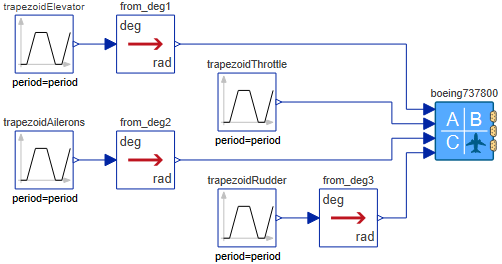
Figure 1: Diagram view of basic model to simulate the flight of a state space aircraft model by giving control commands directly to the control actuators.
If an autopilot is to be used to control the aircraft, the Autopilots.AutopilotStateSpace model is to be added to the top-level model to translate its input signals describing the desired flight trajectory, i.e altitude (altCmd), velocity (vtotCmd) and track angle (trackCmd) into control actuator perturbations. The units for the autopilot inputs are the standard SI units (m, m/s, rad). Figure 2 shows a simple model simulating a flight of a state space aircraft model controlled by an autopilot, where converters from the Modelica.Blocks.Math.UnitConversions package are used to enable entering the velocity and track angle in km/h and degrees, respectively.
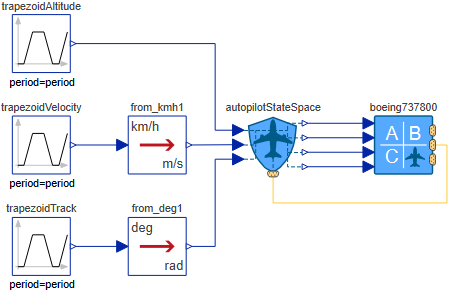
Figure 2: Diagram view of basic model to simulate the flight of a state space aircraft model controlled by an autopilot.
To send feedback from the aircraft position and orientation to the autopilot, the position connector of the aircraft model needs to be connected with the positionSignalBus connector of the autopilot model. The Autopilots.AutopilotStateSpace model is by default tuned for Boeing 737-800 and Douglas DC-8 models and may thus require retuning if used with aircraft of largely different characteristics.
Last, the aircraft model needs to be initialized by entering altitude, total velocity and flight path angle in the Initialization tab for declaring the flight conditions for which the aircraft is trimmed and around which the linearization is done. Once simulated, the most interesting variables are found in the position connector of the aircraft model, including altitude, velocity and orientation of the aircraft.
Creating a New State Space Aircraft Model
A new state space aircraft model can be modeled by creating a new model that extends the StateSpace.FixedWing.DefaultAircraft aircraft model. All properties of the aircraft design are entered on the top level of this new aircraft model into the Aerodynamic Coefficients, Physical Properties, Propulsion and Controls tabs. By default, many properties are derived from the parameters set into the above-mentioned categories, and they are shown in the Derived Properties tab where the equations for estimating the property values are shown. They may be overwritten with known values.
Wolfram Language
In[1]:=
SystemModel["Aircraft.StateSpace"]
Out[1]:=