WOLFRAM SYSTEM MODELER
FailureModelingA model for the study of reliability in a motor |
|
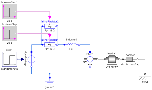
Diagram
Wolfram Language
In[1]:=
SystemModel["DocumentationExamples.Modeling.FailureModeling"]
Out[1]:=
Information
A simple dynamic model of a controlled DC motor consisting of a variable voltage source, a couple of failing resistors, an inductor, and an electro-motoric force element representing the coupling between electric energy and mechanical energy provided by the magnetic field in the DC motor. The motor axis is represented by a damped rotating inertia. Reliability annotations have been added to various components in the model. Boolean step sources determine the time at which the resistors fail.
Components (12)
| failingResistor1 |
Type: FailingResistor Description: Ideal linear electrical resistor with boolean input controlling failure time |
|
|---|---|---|
| failingResistor2 |
Type: FailingResistor Description: Ideal linear electrical resistor with boolean input controlling failure time |
|
| inductor1 |
Type: Inductor Description: Ideal linear electrical inductor |
|
| EMF1 |
Type: RotationalEMF Description: Electromotoric force (electric/mechanic transformer) |
|
| ground1 |
Type: Ground Description: Ground node |
|
| signalVoltage1 |
Type: SignalVoltage Description: Generic voltage source using the input signal as source voltage |
|
| step1 |
Type: Step Description: Generate step signal of type Real |
|
| booleanStep |
Type: BooleanStep Description: Generate step signal of type Boolean |
|
| booleanStep1 |
Type: BooleanStep Description: Generate step signal of type Boolean |
|
| fixed |
Type: Fixed Description: Flange fixed in housing at a given angle |
|
| damper |
Type: Damper Description: Linear 1D rotational damper |
|
| inertia1 |
Type: Inertia Description: 1D-rotational component with inertia |