WOLFRAM SYSTEM MODELER
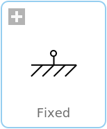
FixedFlange fixed in housing at a given angle |
|
Wolfram Language
In[1]:=
SystemModel["Modelica.Mechanics.Rotational.Components.Fixed"]
Out[1]:=
Information
This information is part of the Modelica Standard Library maintained by the Modelica Association.
The flange of a 1D rotational mechanical system is fixed at an angle phi0 in the housing. May be used:
- to connect a compliant element, such as a spring or a damper, between an inertia or gearbox component and the housing.
- to fix a rigid element, such as an inertia, with a specific angle to the housing.
Parameters (1)
| phi0 |
Value: 0 Type: Angle (rad) Description: Fixed offset angle of housing |
|---|
Connectors (1)
| flange |
Type: Flange_b Description: (right) flange fixed in housing |
|---|
Used in Examples (9)
|
Modelica.Mechanics.Rotational.Examples First example: simple drive train |
|
|
Modelica.Mechanics.Rotational.Examples First example: simple drive train with grounded elements |
|
|
Modelica.Mechanics.Rotational.Examples Drive train with clutch and brake |
|
|
Modelica.Mechanics.Rotational.Examples Drive train with 3 dynamically coupled clutches |
|
|
Modelica.Mechanics.Rotational.Examples Example to show that gear efficiency may lead to stuck motion |
|
|
Modelica.Mechanics.Rotational.Examples Example to show combination of LossyGear and BearingFriction |
|
|
Modelica.Mechanics.Rotational.Examples Example to show possible usage of support flange |
|
|
Modelica.Mechanics.Rotational.Examples Example to demonstrate backlash |
|
|
Modelica.Mechanics.Rotational.Examples Demonstrate the modeling of heat losses |
Used in Components (11)
|
Modelica.Electrical.Analog.Basic Electromotoric force (electric/mechanic transformer) |
|
|
Modelica.Electrical.Machines.Sensors Mechanical power = torque x speed |
|
|
Modelica.Electrical.Machines.Sensors Rotor lagging angle |
|
|
Modelica.Electrical.Machines.Interfaces Partial model for all machines |
|
|
Modelica.Magnetic.FundamentalWave.BaseClasses Base model of machines |
|
|
Modelica.Magnetic.QuasiStatic.FundamentalWave.Sensors Rotor lagging angle |
|
|
Modelica.Magnetic.QuasiStatic.FundamentalWave.BaseClasses Base model of machines |
|
|
Modelica.Mechanics.MultiBody.Joints Revolute joint (1 rotational degree-of-freedom, 2 potential states, optional axis flange) |
|
|
Modelica.Mechanics.Rotational.Interfaces Partial model for a component with one rotational 1-dim. shaft flange and a support used for graphical modeling, i.e., the model is build up by drag-and-drop from elementary components |
|
|
Modelica.Mechanics.Rotational.Interfaces Partial model for a component with two rotational 1-dim. shaft flanges and a support used for graphical modeling, i.e., the model is build up by drag-and-drop from elementary components |
|
|
PartialElementaryRotationalToTranslational Modelica.Mechanics.Rotational.Interfaces Partial model to transform rotational into translational motion |