WOLFRAM SYSTEM MODELER
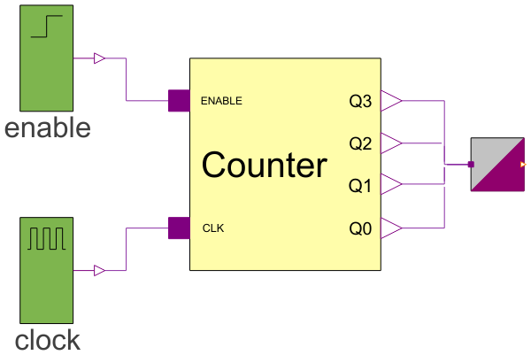
FourBitCounterDemonstration model with a counter, clocks and a binary to integer converter |
|
Diagram
Wolfram Language
In[1]:=
SystemModel["EducationExamples.ElectricalEngineering.BinaryCounter.FourBitCounter"]
Out[1]:=
Information
This model studies how a simple 4-bit binary counter may be set up. Counters can be used for a huge array of applications. They can, for example, be used to count pulses from a sensor attached to a wheel to count the number of revolutions, which in turn can be used to calculate the speed of the wheel. Counters also can be used as digital clocks for different purposes. Another typical use of a digital counter is in central processing units (CPUs), where a certain kind of counter (program counters, or PCs) is used as a way for the CPU to walk through program instructions, one by one, from a memory.
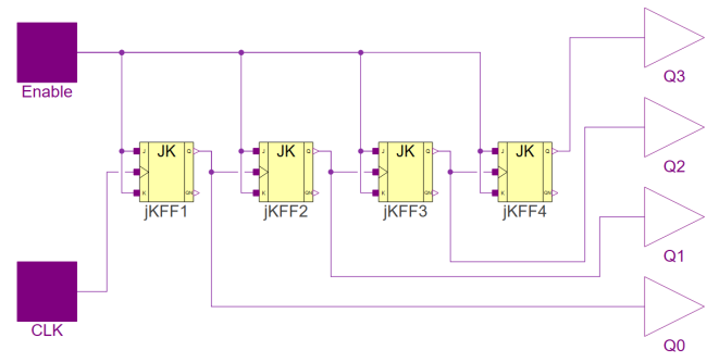
Counter Model
The counter in this example is a 4-bit asynchronous counter based on JK flip-flops. For more details about the counter and how it works, you can check out the documentation for the counter model in the components package of this example.
Simulation
By simulating the model, you can get the graphs for the output of the four output pins and how they relate to one another. You will quickly see that an output toggles when its "lower neighbor" goes from 1 to 0.
To simulate the model, Click the Simulate button:  . You will be presented with a graph showing the state of the four output pins with respect to time. If you want to plot other states, you can make a new plot by clicking the New Plot Window button:
  . You can then choose which variables you want to plot. If you want to plot the clock signal, you just expand the Clock object under the Plot tab and check the box labeled "y". If you would like to plot the new variable together with the outputs instead of a new plot, you can just add another subplot by clicking the New Plot Window button:
Expanding the Model
If you would like to play around with this model and expand it by adding more flip-flops to make it count even higher, you can examine how the model works and just drag more flip-flops into the model and connect them accordingly. You can find the JK flip-flop and other flip-flops in the Modelica Standard Library under Electrical▸Digital▸Examples▸Utilities. You can also adjust the clock speed by clicking the Clock element in the ExampleModel diagram. Under the tab labeled General, choose how long a period should be and for how what percent of the period the signal should be 1. Why not be a little adventurous and use the ModelPlug library to connect a sensor via an Arduino and make the model count the number of pulses it generates?
Components (4)
| fourBitCounter |
Type: Counter Description: 4-bit asynchronous counter. |
|
|---|---|---|
| enable |
Type: Step Description: Enable signal to the counter. |
|
| clock |
Type: DigitalClock Description: Clock signal to the counter. |
|
| integerOutput |
Type: BinaryToIntegerConverter Description: Converted integer output from boolean states. |