WOLFRAM SYSTEM MODELER
Counter4-bit asychronous counter |
|
Diagram
Wolfram Language
In[1]:=

SystemModel["EducationExamples.ElectricalEngineering.BinaryCounter.Components.Counter"]
Out[1]:=
Information
4-Bit Binary Counter
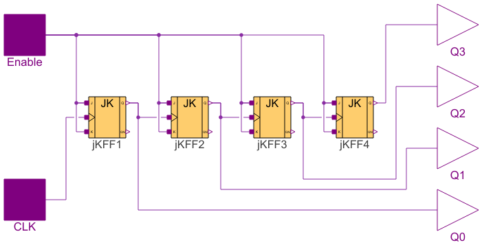
The counter in this example is a 4-bit asynchronous counter based on JK flip-flops. The flip-flops are connected with both their J and K terminals to the enable pin, putting them in "toggle mode".

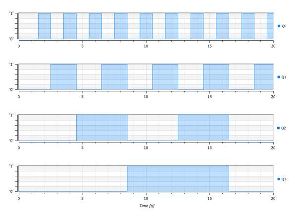
The flip-flop to the left will change its output state for each falling edge of the clock signal, which means that the output can be toggled with a button or a CPU clock, for example. In this particular case, it is convenient to think of this as a sort of "slowdown" from each flip-flop to the next. Since the output toggles for each falling edge of the clock, the clock toggles twice for each toggle of the output. If you connect the first flip-flop's output as a clock signal to flip-flop number two, the same thing will happen there, so the frequency will go down by half for each flip-flop.
You can also compare this to how the mileage indicator on an old car works. There, the digits go from 0 to 9, and the first digit to the right indicates hundreds of meters, the second one indicates kilometers, the third one tens of kilometers, etc. In this case, the second digit "wants to know" when the first digit turns around to zero again so that it can count up by one. The same thing goes for the third digit. When the second digit goes around to zero, this is indicated by raising the value of the third digit. Since working in binary only requires two states, when the first digit decreases by one (goes from 1 to 0), the second digit gets increased by one. In binary you increase the value just by toggling from 0 to 1 or 1 to 0, so no actual counting is needed.
JK Flip-Flops
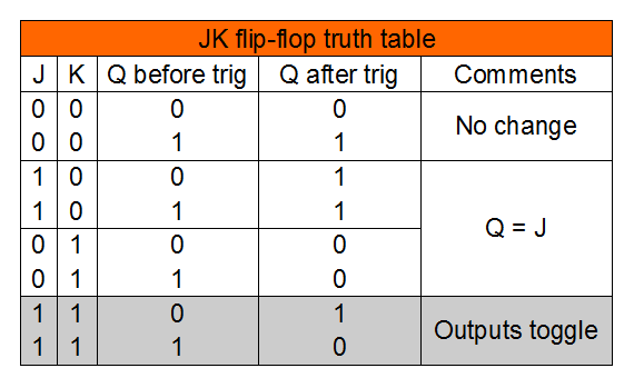
Flip-flops or latches are used as basic components in digital circuitry and work as a kind of memory that stores the state of one bit. By using multiple flip-flops, it is possible to construct digital state machines. A binary counter is basically a state machine that just cycles through its states for each cycle of a clock signal. The JK flip-flop is considered to be the most universal flip-flop design and can be used as different kinds of flip-flops just by adjusting how the input to the J and K terminals is done. In this example, the flip-flops are used with a toggling function, which means that the output is changed for each completed clock cycle. This is accomplished by feeding ones into both the J and K pins of the flip-flops. By putting only zeros on all the J and K terminals, the output will never change, regardless of the input. This makes it suitable to connect all the J and K terminals as an enable signal for the circuit. Below, you can see the truth table for JK flip-flops. The row of interest to us is marked with gray.
Connectors (6)
| Enable |
Type: DigitalInput Description: Input enable signal |
|
|---|---|---|
| CLK |
Type: DigitalInput Description: Input clock signal |
|
| Q0 |
Type: DigitalOutput Description: Output pin 0 |
|
| Q1 |
Type: DigitalOutput Description: Output pin 1 |
|
| Q2 |
Type: DigitalOutput Description: Output pin 2 |
|
| Q3 |
Type: DigitalOutput Description: Output pin 3 |
Components (4)
Used in Examples (1)
|
EducationExamples.ElectricalEngineering.BinaryCounter Demonstration model with a counter, clocks and a binary to integer converter |