WOLFRAM SYSTEM MODELER
InverterConverts from DC to AC |
|
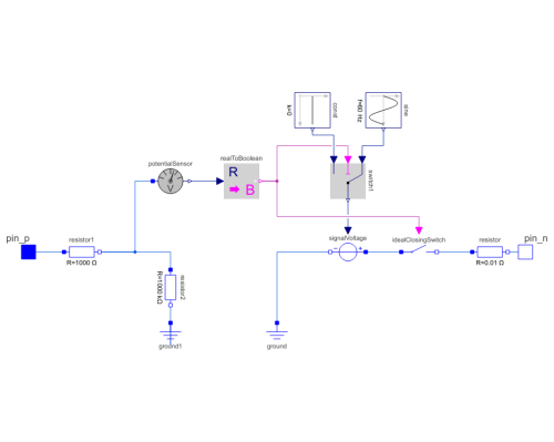
Diagram
Wolfram Language

SystemModel["EducationExamples.ElectricalEngineering.UPS.Components.Inverter"]

Information
Parameters (1)
| lowerVoltageLimit |
Value: Type: Voltage (V) Description: Limit where the inverter can't supply full voltage |
|---|
Connectors (2)
| pin_p |
Type: PositivePin Description: Positive pin of an electrical component |
|
|---|---|---|
| pin_n |
Type: NegativePin Description: Negative pin of an electrical component |
Components (12)
| signalVoltage |
Type: SignalVoltage Description: Generic voltage source using the input signal as source voltage |
|
|---|---|---|
| potentialSensor |
Type: PotentialSensor Description: Sensor to measure the potential |
|
| ground |
Type: Ground Description: Ground node |
|
| sine |
Type: Sine Description: Generate sine signal |
|
| switch1 |
Type: Switch Description: Switch between two Real signals |
|
| realToBoolean |
Type: RealToBoolean Description: Convert Real to Boolean signal |
|
| const |
Type: Constant Description: Generate constant signal of type Real |
|
| resistor |
Type: Resistor Description: Ideal linear electrical resistor |
|
| idealClosingSwitch |
Type: IdealClosingSwitch Description: Ideal electrical closer |
|
| ground1 |
Type: Ground Description: Ground node |
|
| resistor1 |
Type: Resistor Description: Ideal linear electrical resistor |
|
| resistor2 |
Type: Resistor Description: Ideal linear electrical resistor |
Used in Examples (2)
|
EducationExamples.ElectricalEngineering.UPS Model of an uninterruptible power supply that controls the supply of power to a load. |
|
|
EducationExamples.ElectricalEngineering.UPS Model of a uninterruptible power supply with a non-standard battery reliability. |

