WOLFRAM SYSTEM MODELER
BatteryBattery to keep the equipment going through power failure |
|
Diagram
Wolfram Language
In[1]:=
SystemModel["IndustryExamples.Energy.UPS.Components.Battery"]
Out[1]:=
Information
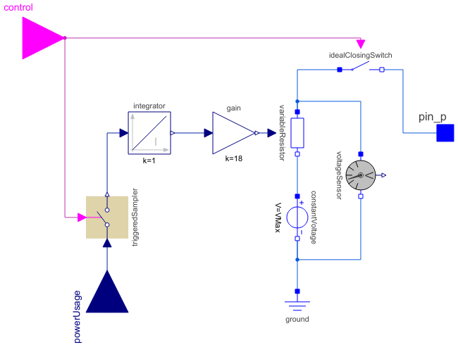
The battery turns on when the control signal is true. The charge left in the battery is modeled with a variable resistor. More power usage (from powerUsage) will lead to a shorter uptime.
Parameters (1)
| VMax |
Value: 10 Type: Voltage (V) Description: Battery cell voltage when fully charged |
|---|
Connectors (4)
| pin_p |
Type: PositivePin Description: Positive pin of an electrical component |
|
|---|---|---|
| control |
Type: BooleanInput Description: 'input Boolean' as connector |
|
| powerUsage |
Type: RealInput Description: Instant power usage |
|
| V |
Type: RealOutput Description: Battery cell voltage |
Components (8)
| constantVoltage |
Type: ConstantVoltage Description: Source for constant voltage |
|
|---|---|---|
| ground |
Type: Ground Description: Ground node |
|
| idealClosingSwitch |
Type: IdealClosingSwitch Description: Ideal electrical closer |
|
| variableResistor |
Type: VariableResistor Description: Ideal linear electrical resistor with variable resistance |
|
| gain |
Type: Gain Description: Output the product of a gain value with the input signal |
|
| triggeredSampler |
Type: TriggeredSampler Description: Triggered sampling of continuous signals |
|
| integrator |
Type: Integrator Description: Output the integral of the input signal with optional reset |
|
| voltageSensor |
Type: VoltageSensor Description: Sensor to measure the voltage between two pins |
Used in Examples (2)
|
IndustryExamples.Energy.UPS Model of an uninterruptible power supply that controls the supply of power to a load. |
|
|
IndustryExamples.Energy.UPS Model of a uninterruptible power supply with a non-standard battery reliability. |