WOLFRAM SYSTEMMODELER
BlockCircuitA block based approach to modeling of an electrical circuit |
|
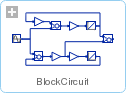
Diagram

Wolfram Language
In[1]:=

SystemModel["IntroductoryExamples.ComponentBased.BlockCircuit"]
Out[1]:=
Information
This is a block based model of the circuit below.
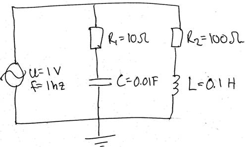
The signal voltage is considered as input and the signal current as output. The system is derived from the following three equations


where i, is the total current through the signal voltage, i1 and i2 are the currents running through resistor 1 and 2 respectively. Using the Laplace transform the above equations and resolve i as a function of u.


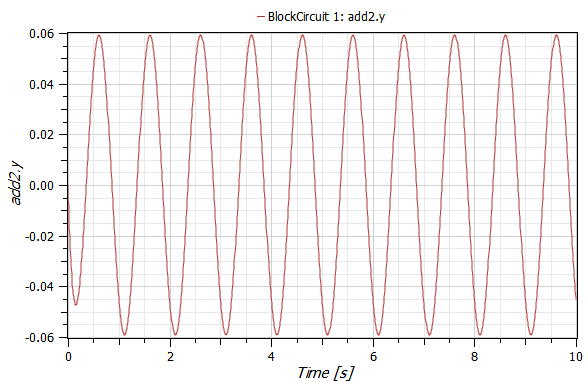
The output current is the result of add2, i1 and i2 are the signals from gain3 and integrator1 respectively. The picture below shows the resulting current:
A component based version of this model can be found here.
For a step by step tutorial see Component-Based—Simple Circuit.
Components (10)
| gain3 |
Type: Gain Description: |
|
|---|---|---|
| gain1 |
Type: Gain Description: |
|
| add3 |
Type: Add Description: |
|
| gain4 |
Type: Gain Description: |
|
| sine1 |
Type: Sine Description: |
|
| integrator1 |
Type: Integrator Description: |
|
| add1 |
Type: Add Description: |
|
| add2 |
Type: Add Description: |
|
| gain2 |
Type: Gain Description: |
|
| integrator2 |
Type: Integrator Description: |