WOLFRAM SYSTEM MODELER
GettingStartedStep-by-step guide to running your first model using ModelPlug |
|
Information
This guide assumes that you have an Arduino (or Firmata-compatible board) and basic knowledge on how to use it. If you are just starting with the Arduino, we recommend you to first visit the Arduino webpage, http://arduino.cc, and have a look at the “Getting Started” guide. Before continuing, please ensure that you can upload Arduino examples to your board and that it is working correctly. This guide uses Arduino IDE v2.x.
Preparing Your Board
Basic knowledge of System Modeler is assumed for this guide. If you do not have ModelPlug installed on your computer, please go ahead and install it. We recommend that you have a look at the learning resources at http://www.wolfram.com/system-modeler/resources if you are not familiar with System Modeler.
The first thing you need to do is to upload the Firmata code to your board. For Arduino IDE v2.x, you need to install the Firmata library using the Library Manager. Open the Library Manager (see Figure 1), search for "Firmata" and click the install button to download it. In Arduino v1.x, the Firmata library comes pre-installed.
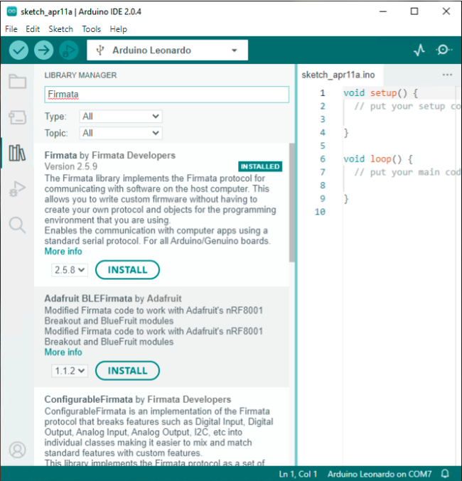
Figure 1. Installing the Firmata library.
Once the library is installed, in the menu, click Files > Examples > Firmata > StandardFirmata (see Figure 2).
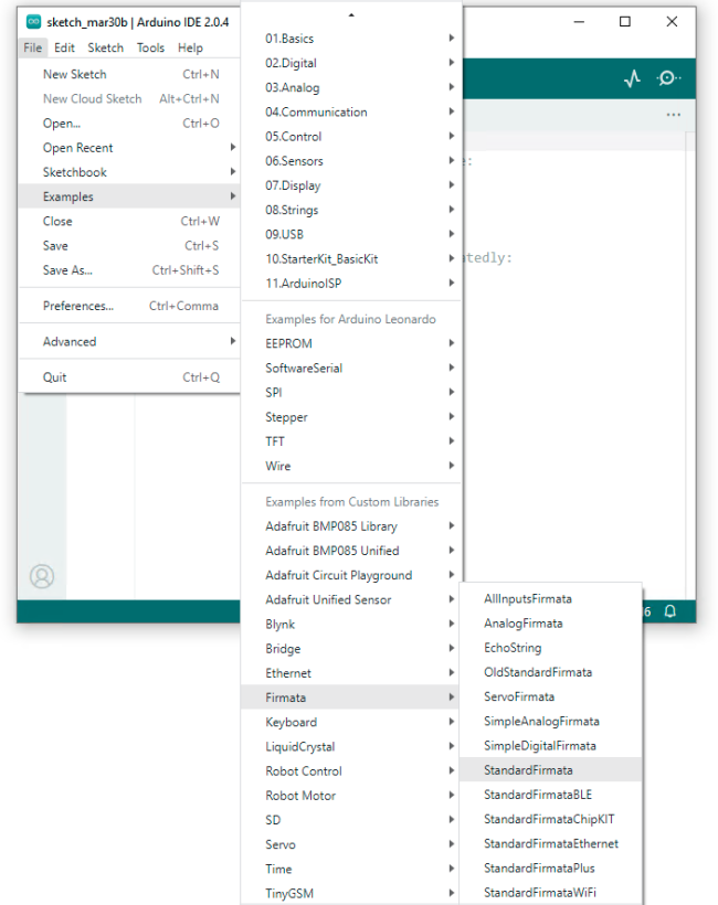
Figure 2. Location of the Firmata sketch.
Once you have opened the StandardFirmata sketch you need to upload it. Connect your Arduino board and select the board type from the menu as shown in Figure 3. Press the upload button and wait for the program to be compiled and flashed.
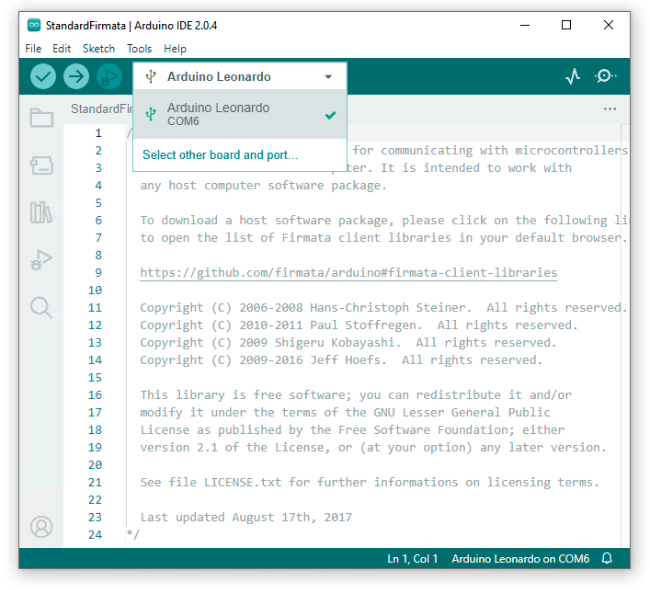
Figure 3. Selecting the Arduino board.
Once the Firmata upload has fininshed, write down the serial port name as you will need to give the port name to ModelPlug later in order to communicate with the board. The serial port name can be found under the menu Tools > Serial Port or in the bottom-right corner of the Arduino software window (see Figure 4). In Windows, the serial port name is something like “COM5”, while in MacOS and Linux the name will be something like “/dev/ttyACM0”. You are now ready to create your first model.
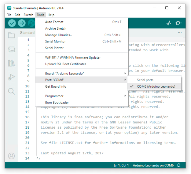
Figure 4. Finding the serial port being used.
Blinking LED
As a first exercise, with the purpose of introducing ModelPlug, you are going to recreate the ModelPlug blinking LED example model. To build the model, create a new model and drag & drop the following components from the Class Browser to the diagram view of your model:
- ModelPlug.Pins.DigitalOutput
- ModelPlug.Boards.Arduino
- Modelica.Blocks.Sources.BooleanPulse
Connect the components as in Figure 5. The 'DigitalOutput' component is connected to the 'Arduino' component in order to associate a specific pin to a specific board. This is necessary as multiple boards with multiple pins can be used at the same time.
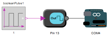
Figure 5. Diagram of the blinking LED.
Next, specify the serial port that the board is going to be using. Select the 'Arduino' component in the diagram view to list its parameters. In the parameter view, locate the 'Port' parameter and click the icon to the right of its text box to bring up the Serial Port Selector window. Select the port you obtained from section “Preparing your board”. If you manually type the name of the port, ensure that the name is surrounded by quotation marks, as shown in Figure 6.
Note that some Arduino boards, such as the Leonardo, require that the 'UseDTR' parameter is set to true. If you are not sure whether your board requires it, you can always go back and change it later if the board would not be responding.
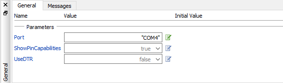
Figure 6. Specifying the serial port name.
Earlier you associated an output pin to the board by creating a connection between two components. Now you need to specify what output pin you are going to use. Select the 'DigitalOutput' component and set the 'Pin' parameter to the number of the pin. Arduino boards usually have an LED attached to pin 13.
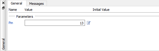
Figure 7. Specifying the pin to use.
Finally, for the 'BooleanPulse' component, set the 'period' parameter to 1. The model is now ready to simulate. Press the simulate button in the tool bar to build and simulate the model.
The first time you run the simulation it will probably finish without you noticing the LED blinking even once. The reason for this is that System Modeler performs the simulation of the model as fast as possible. In order to interact with your models using ModelPlug, it is necessary to synchronize the simulation time with real-time. This is done in Simulation Center. After the first simulation of the model, check the the checkbox 'Synchronize with real-time' in the Settings view of the Experiment Browser, as shown in Figure 8.
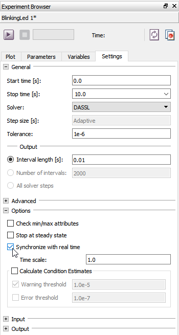
Figure 8. Synchronizing your simulation with real time.
If you plan on creating many models with the ModelPlug library, you probably want to make the “Synchronize with real-time” setting the default setting. This is done in Simulation Center under the menu Tools > Options in the section Simulation Center > Default Experiment (see Figure 9).
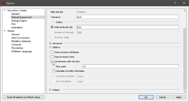
Figure 9. Setting "Synchronize with real-time" as default.
Run the simulation again and you should see the LED blinking until the simulation reaches the stop time. If you want to keep the simulation running continuously, you need to change the stop time to infinity as shown in Figure 10.
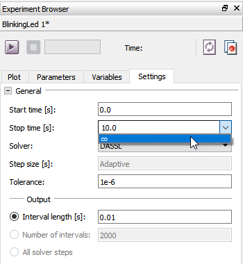
Figure 10. Setting the stop time to infinity.
If you run the simulation again, you should see the LED blinking continuously.
One thing that you may have noticed is that ModelPlug prints messages in the Simulation Log view when the simulation is started (see Figure 11). The messages are explained below:
- A. A list of all available serial ports.
- B. The name and speed of the currently used serial port.
- C. A confirmation that the board was successfully initialized. The board's Firmata version is usually shown here.
- D. The sampling interval for the board is set.
- E. A list of all pin configurations. In this example, pin 13 is set to be an output as a result of the configuration of the 'DigitalOutput' component done earlier.
- F. A list of all available pins and their capabilities. This list contains the numbers of the pins and the modes in which they can be used.
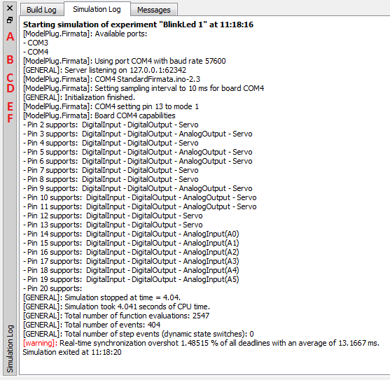
Figure 11. Messages shown by ModelPlug.
Troubleshooting
Here is checklist that you can follow in order to solve most of the problems that can occur when using the ModelPlug library:
- Verify that you can upload Arduino examples to your board.
- Verify that you have uploaded the StandardFirmata example to your board.
- Verify that the port name in the board component in the model matches the port name of the connected board.
- Verify that the port name is surrounded by quotation marks.
- ModelPlug will not be able to connect to the board if there is another application using the port. Ensure that no other application is using the port.
- If the simulation log does not show the board capabilities, try uploading the Firmata to your board again.
- When using multiple boards, your operating system may have changed the port names. Verify that the port names in the board components match to port names of the hardware boards.
- Some Arduino boards, such as the Leonardo, require the 'UseDTR' parameter to be set to true. Change the parameter and try again.
If you are still having problems, we recommend a visit to http://community.wolfram.com where you ask questions and connect with other users of ModelPlug.
What Next?
ModelPlug contains a series of basic examples showing the functionality of the components. The examples can be found under ModelPlug.Examples. Once you have learned how to use the basic components of ModelPlug, visit the Arduino Playground to learn how to connect other sensors and actuators.
Wolfram Language
In[1]:=
SystemModel["ModelPlug.GettingStarted"]
Out[1]:=