WOLFRAM SYSTEM MODELER
ClocksClocks |
|
Wolfram Language
SystemModel["Modelica.Clocked.UsersGuide.Clocks"]

Information
This information is part of the Modelica Standard Library maintained by the Modelica Association.
A central element of the Modelica.Clocked library is a clock. Below, the most important information for clocks is summarized. For more details, see the Modelica Language Specification, Chapter 16 (for Modelica Language Version ≥ 3.3).
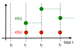
A Clock type is a base data type (introduced in Modelica 3.3, additionally to Real, Integer, Boolean, String) that defines when a particular partition consisting of a set of equations is active. Starting with Modelica Language Version 3.3, every variable and every equation is either continuous-time or is associated exactly to one clock. This feature is visualized in the figure below where c(ti) is a clock that is active at particular time instants ti and r(ti) is a variable that is associated to this clock. A clocked variable has only a value when the corresponding clock is active:

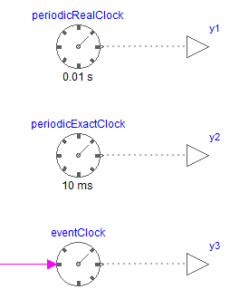
Similarly to RealInput, RealOutput etc., clock input and output connectors, called ClockInput and ClockOutput, are defined in sublibrary ClockSignal.Interfaces in order to propagate clocks via connections. A clock signal can be generated with one of the blocks of sublibrary ClockSignals.Clocks:

The output signals of the blocks in the above figure are clock signals, by default visualized with dotted grey lines.
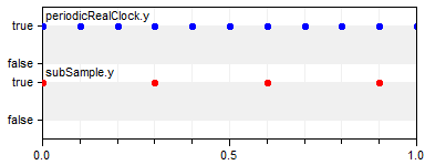
With the blocks of sublibrary ClockSignals.Sampler a clock signal can be sub-sampled, super-sampled, or shift-sampled to generate a new clock signal. For example, with the following model, a periodic clock signal of 0.1 s is sub-sampled with a factor 3 and therefore a clock signal with a period of 0.3 s is generated:


As usual in synchronous languages, a clock is represented by a true value when the clock is active. The relationship between such derived clocks is exact, so it is guaranteed that at every 3rd tick of clock "periodicRealClock.y", the clock "subSample.y" is active.
If a clock is associated to a clocked continuous-time partition, then an integrator has to be defined that is used to integrate the partition from the previous to the current clock tick. This is performed by setting parameter useSolver = true and defining the integration method as String with parameter solver. Both parameters are in tab Advanced of one of the clock signal generating blocks. The possible integration methods are tool dependent. It is expected that at least the solvers "External" (= use the integrator selected in the simulation environment) and "ExplicitEuler" (= explicit Euler method) are supported by every tool. For an example, see Examples.Systems.ControlledMixingUnit.
A clocked partition is a set of equations that depend on each other and where the boundary variables are marked with sample and hold operators. If a clocked partition contains no operator der, delay, spatialDistribution, no event related operators (with exception of noEvent(…)), and no when-clause with a Boolean condition, it is a clocked discrete-time partition, that is, it is a standard sampled data system that is described by difference equations. If a clocked partition is not a clocked discrete-time partition and it contains neither operator previous nor operator interval, it is a clocked discretized continuous-time partition. Such a partition has to be solved with a solver method. It is an error, if none of the two properties hold, e.g., if operators previous and der are both used in the same partition. In a clocked discrete-time partition all event generating mechanisms do no longer apply. Especially neither relations, nor one of the built-in event triggering operators will trigger an event.
