WOLFRAM SYSTEM MODELER
CauerLowPassOPVCauer low pass filter with operational amplifiers |
|
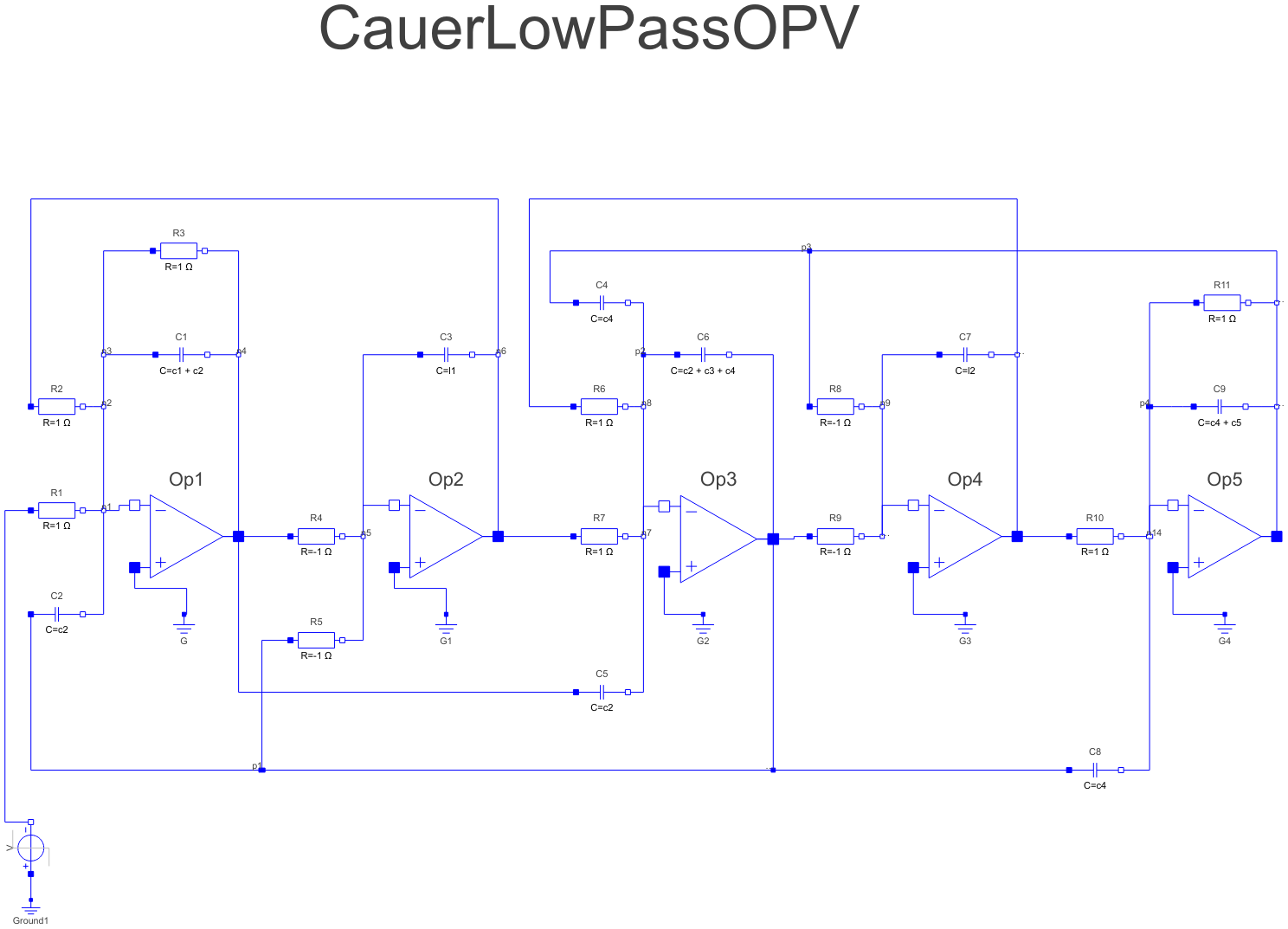
Diagram
Wolfram Language
In[1]:=
SystemModel["Modelica.Electrical.Analog.Examples.CauerLowPassOPV"]
Out[1]:=
Information
This information is part of the Modelica Standard Library maintained by the Modelica Association.
The example Cauer Filter is a low-pass-filter of the fifth order. It is realized using an analog network with operational amplifiers. The voltage source V is the input voltage (step), and the OP5.out.v is the filter output voltage. The pulse response is calculated.
This model is identical to the CauerLowPassAnalog example, but inverting. To get the same response as that of the CauerLowPassAnalog example, a negative voltage step is used as input.
The simulation end time should be 60. Please plot both V.v (which is the inverted input voltage) and OP5.p.v (output voltage). Compare this result with the CauerLowPassAnalog result.
During translation some warnings are issued concerning resistor values (Value=-1 not in range [0,1e100]). Do not worry about it. The negative values are o.k.
Parameters (7)
| l1 |
Value: 1.304 Type: Capacitance (F) Description: Filter coefficient i1 |
|---|---|
| l2 |
Value: 0.8586 Type: Capacitance (F) Description: Filter coefficient i2 |
| c1 |
Value: 1.072 Type: Capacitance (F) Description: Filter coefficient c1 |
| c2 |
Value: 1 / (1.704992 ^ 2 * l1) Type: Capacitance (F) Description: Filter coefficient c2 |
| c3 |
Value: 1.682 Type: Capacitance (F) Description: Filter coefficient c3 |
| c4 |
Value: 1 / (1.179945 ^ 2 * l2) Type: Capacitance (F) Description: Filter coefficient c4 |
| c5 |
Value: 0.7262 Type: Capacitance (F) Description: Filter coefficient c5 |
Components (32)
| C1 |
Type: Capacitor Description: Ideal linear electrical capacitor |
|
|---|---|---|
| C2 |
Type: Capacitor Description: Ideal linear electrical capacitor |
|
| C3 |
Type: Capacitor Description: Ideal linear electrical capacitor |
|
| C4 |
Type: Capacitor Description: Ideal linear electrical capacitor |
|
| C5 |
Type: Capacitor Description: Ideal linear electrical capacitor |
|
| R1 |
Type: Resistor Description: Ideal linear electrical resistor |
|
| R2 |
Type: Resistor Description: Ideal linear electrical resistor |
|
| R3 |
Type: Resistor Description: Ideal linear electrical resistor |
|
| Op1 |
Type: IdealOpAmp3Pin Description: Ideal operational amplifier (norator-nullator pair), but 3 pins |
|
| G |
Type: Ground Description: Ground node |
|
| R4 |
Type: Resistor Description: Ideal linear electrical resistor |
|
| R5 |
Type: Resistor Description: Ideal linear electrical resistor |
|
| Op2 |
Type: IdealOpAmp3Pin Description: Ideal operational amplifier (norator-nullator pair), but 3 pins |
|
| Op3 |
Type: IdealOpAmp3Pin Description: Ideal operational amplifier (norator-nullator pair), but 3 pins |
|
| G1 |
Type: Ground Description: Ground node |
|
| R6 |
Type: Resistor Description: Ideal linear electrical resistor |
|
| R7 |
Type: Resistor Description: Ideal linear electrical resistor |
|
| C6 |
Type: Capacitor Description: Ideal linear electrical capacitor |
|
| R8 |
Type: Resistor Description: Ideal linear electrical resistor |
|
| R9 |
Type: Resistor Description: Ideal linear electrical resistor |
|
| R10 |
Type: Resistor Description: Ideal linear electrical resistor |
|
| Op4 |
Type: IdealOpAmp3Pin Description: Ideal operational amplifier (norator-nullator pair), but 3 pins |
|
| Op5 |
Type: IdealOpAmp3Pin Description: Ideal operational amplifier (norator-nullator pair), but 3 pins |
|
| C7 |
Type: Capacitor Description: Ideal linear electrical capacitor |
|
| C8 |
Type: Capacitor Description: Ideal linear electrical capacitor |
|
| C9 |
Type: Capacitor Description: Ideal linear electrical capacitor |
|
| R11 |
Type: Resistor Description: Ideal linear electrical resistor |
|
| G2 |
Type: Ground Description: Ground node |
|
| G3 |
Type: Ground Description: Ground node |
|
| G4 |
Type: Ground Description: Ground node |
|
| V |
Type: StepVoltage Description: Step voltage source |
|
| Ground1 |
Type: Ground Description: Ground node |
Revisions
- January 13, 2006
by Christoph Clauss
included into Modelica Standard Library - September 15, 2005
by Peter Trappe designed and by Teresa Schlegel
initially modelled.