WOLFRAM SYSTEM MODELER
IdealTriacCircuitIdeal triac test circuit |
|
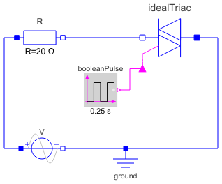
Diagram
Wolfram Language
In[1]:=
SystemModel["Modelica.Electrical.Analog.Examples.IdealTriacCircuit"]
Out[1]:=

Information
This information is part of the Modelica Standard Library maintained by the Modelica Association.
The simple ideal TRIAC example shows how a triac is used within an alternating current circuit.
The TRIAC is not conducting until the Boolean input becomes true (internally coded by 1, therefore the input is called fire1). Then it becomes "conducting", the knee voltage is reached. If the TRIAC voltage falls below the knee voltage, the TRIAC becomes blocking. Due to the antiparallel connection of the internal two thyristors the same behavior is repeated in the negative half-wave.
Simulate until 2 seconds. Display V.p.v (input voltage), booleanPulse.y (fire1 input), and both idealTriac.n.v and idealTriac.n.i, which demonstrate the TRIAC behavior.
Components (5)
| ground |
Type: Ground Description: Ground node |
|
|---|---|---|
| R |
Type: Resistor Description: Ideal linear electrical resistor |
|
| V |
Type: SineVoltage Description: Sine voltage source |
|
| booleanPulse |
Type: BooleanPulse Description: Generate pulse signal of type Boolean |
|
| idealTriac |
Type: IdealTriac Description: Ideal triac, based on ideal thyristors |
Revisions
- November 25, 2009
by Susann Wolf