WOLFRAM SYSTEM MODELER
FirstOrderLowpass filter operational amplifier circuit |
|
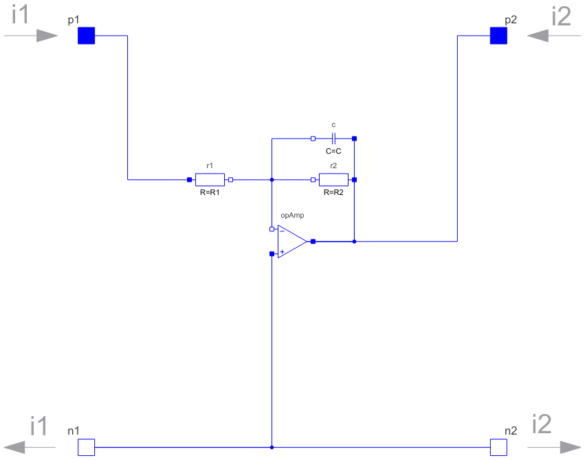
Diagram
Wolfram Language
In[1]:=
SystemModel["Modelica.Electrical.Analog.Examples.OpAmps.OpAmpCircuits.FirstOrder"]
Out[1]:=
Information
This information is part of the Modelica Standard Library maintained by the Modelica Association.
Inverting lowpass filter = first order, based on the IdealizedOpAmpLimited model.
Transfer function: vOut/vIn = -k/(1 + s*T)
Parameters (8)
| Vps |
Value: +15 Type: Voltage (V) Description: Positive supply |
|---|---|
| Vns |
Value: -15 Type: Voltage (V) Description: Negative supply |
| V0 |
Value: 15000.0 Type: Real Description: No-load amplification |
| k |
Value: 1 Type: Real Description: Desired amplification |
| R1 |
Value: 1000 Type: Resistance (Ω) Description: Resistance at negative input of OpAmp |
| R2 |
Value: k * R1 Type: Resistance (Ω) Description: Calculated resistance to reach k |
| T |
Type: Time (s) Description: Time constant |
| C |
Value: T / R2 Type: Capacitance (F) Description: Calculated capacitance to reach T |
Connectors (4)
| p1 |
Type: PositivePin Description: Positive electrical pin of port 1 |
|
|---|---|---|
| n1 |
Type: NegativePin Description: Negative electrical pin of port 1 |
|
| p2 |
Type: PositivePin Description: Positive electrical pin of port 2 |
|
| n2 |
Type: NegativePin Description: Negative electrical pin of port 2 |
Components (4)
| opAmp |
Type: IdealizedOpAmpLimited Description: Idealized operational amplifier with limitation |
|
|---|---|---|
| r1 |
Type: Resistor Description: Ideal linear electrical resistor |
|
| r2 |
Type: Resistor Description: Ideal linear electrical resistor |
|
| c |
Type: Capacitor Description: Ideal linear electrical capacitor |
Used in Examples (2)
|
Modelica.Electrical.Analog.Examples.OpAmps Low-pass filter |
|
|
Modelica.Electrical.Analog.Examples.OpAmps Control circuit |