WOLFRAM SYSTEM MODELER
ParallelResonanceParallel resonance circuit |
|
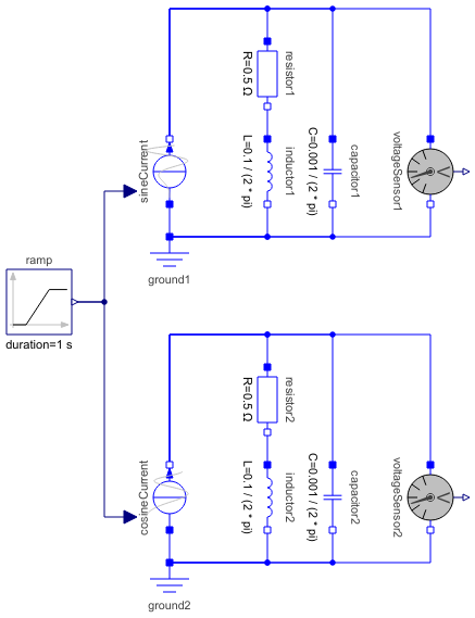
Diagram
Wolfram Language
In[1]:=
SystemModel["Modelica.Electrical.Analog.Examples.ParallelResonance"]
Out[1]:=
Information
This information is part of the Modelica Standard Library maintained by the Modelica Association.
This model demonstrates the transient behaviour of a parallel resonant circuit: A sine or cosine current with variable frequency and constant amplitude is applied to a parallel connection of L, C and R. The parameter values result in a resonance frequency of 100 Hz.
Components (13)
| sineCurrent |
Type: SineCurrentVariableFrequencyAndAmplitude Description: Sine current source with variable frequency and amplitude |
|
|---|---|---|
| ground1 |
Type: Ground Description: Ground node |
|
| resistor1 |
Type: Resistor Description: Ideal linear electrical resistor |
|
| inductor1 |
Type: Inductor Description: Ideal linear electrical inductor |
|
| capacitor1 |
Type: Capacitor Description: Ideal linear electrical capacitor |
|
| voltageSensor1 |
Type: VoltageSensor Description: Sensor to measure the voltage between two pins |
|
| ramp |
Type: Ramp Description: Generate ramp signal |
|
| cosineCurrent |
Type: CosineCurrentVariableFrequencyAndAmplitude Description: Cosine current source with variable frequency and amplitude |
|
| ground2 |
Type: Ground Description: Ground node |
|
| resistor2 |
Type: Resistor Description: Ideal linear electrical resistor |
|
| inductor2 |
Type: Inductor Description: Ideal linear electrical inductor |
|
| capacitor2 |
Type: Capacitor Description: Ideal linear electrical capacitor |
|
| voltageSensor2 |
Type: VoltageSensor Description: Sensor to measure the voltage between two pins |