WOLFRAM SYSTEM MODELER
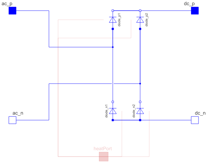
DiodeBridge2PulseTwo pulse Graetz diode rectifier bridge |
|
Diagram
Wolfram Language
In[1]:=
SystemModel["Modelica.Electrical.PowerConverters.ACDC.DiodeBridge2Pulse"]
Out[1]:=

Information
This information is part of the Modelica Standard Library maintained by the Modelica Association.
General information about AC/DC converters can be found at the AC/DC converter concept
This is a two pulse Graetz diode rectifier bridge. The circuit topology is the same as in Examples.ACDC.RectifierCenterTap2Pulse.
Parameters (5)
| RonDiode |
Value: 1e-05 Type: Resistance (Ω) Description: Closed diode resistance |
|---|---|
| GoffDiode |
Value: 1e-05 Type: Conductance (S) Description: Opened diode conductance |
| VkneeDiode |
Value: 0 Type: Voltage (V) Description: Diode forward threshold voltage |
| useHeatPort |
Value: false Type: Boolean Description: = true, if heatPort is enabled |
| T |
Value: 293.15 Type: Temperature (K) Description: Fixed device temperature if useHeatPort = false |
Connectors (5)
| ac_p |
Type: PositivePin Description: Positive AC input |
|
|---|---|---|
| ac_n |
Type: NegativePin Description: Negative AC input |
|
| dc_p |
Type: PositivePin Description: Positive DC output |
|
| dc_n |
Type: NegativePin Description: Negative DC output |
|
| heatPort |
Type: HeatPort_a Description: Conditional heat port |
Components (4)
| diode_p1 |
Type: IdealDiode Description: Diode connecting the positive AC input pin with positive DC output |
|
|---|---|---|
| diode_p2 |
Type: IdealDiode Description: Diode connecting the negative AC input pin with positive DC output |
|
| diode_n1 |
Type: IdealDiode Description: Diode connecting the positive AC input pin with negative DC output |
|
| diode_n2 |
Type: IdealDiode Description: Diode connecting the negative AC input pin with negative DC output |
Used in Examples (1)
|
Modelica.Electrical.PowerConverters.Examples.ACDC.RectifierBridge2Pulse Two pulse Graetz diode bridge with resistive load |