WOLFRAM SYSTEM MODELER
DiodeBridge2PulseTwo pulse Graetz diode bridge with resistive load |
|
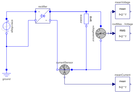
Diagram
Wolfram Language
In[1]:=

SystemModel["Modelica.Electrical.PowerConverters.Examples.ACDC.RectifierBridge2Pulse.DiodeBridge2Pulse"]
Out[1]:=
Information
This information is part of the Modelica Standard Library maintained by the Modelica Association.
This examples shows a two pulse uncontrolled bridge example with resistive load.
Plot current currentSensor.i, average current meanCurrent.y, voltage voltageSensor.v and average voltage meanVoltage.v.
Parameters (3)
| Vrms |
Value: 110 Type: Voltage (V) Description: RMS supply voltage |
|---|---|
| f |
Value: 50 Type: Frequency (Hz) Description: Frequency |
| R |
Value: 20 Type: Resistance (Ω) Description: Load resistance |
Components (9)
| ground |
Type: Ground Description: Ground node |
|
|---|---|---|
| sinevoltage |
Type: SineVoltage Description: Sine voltage source |
|
| rectifier |
Type: DiodeBridge2Pulse Description: Two pulse Graetz diode rectifier bridge |
|
| voltagesensor |
Type: VoltageSensor Description: Sensor to measure the voltage between two pins |
|
| meanVoltage |
Type: Mean Description: Calculate mean over period 1/f |
|
| rootMeanSquareVoltage |
Type: RootMeanSquare Description: Calculate root mean square over period 1/f |
|
| currentSensor |
Type: CurrentSensor Description: Sensor to measure the current in a branch |
|
| meanCurrent |
Type: Mean Description: Calculate mean over period 1/f |
|
| resistor |
Type: Resistor Description: Ideal linear electrical resistor |