WOLFRAM SYSTEM MODELER
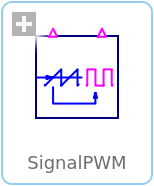
SignalPWMGenerates a pulse width modulated (PWM) boolean fire signal |
|
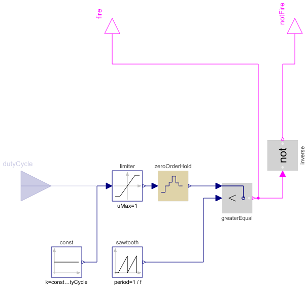
Diagram
Wolfram Language
In[1]:=
SystemModel["Modelica.Electrical.PowerConverters.DCDC.Control.SignalPWM"]
Out[1]:=
Information
This information is part of the Modelica Standard Library maintained by the Modelica Association.
This controller can be used both for DC/DC and AC/DC converters.
The signal input of the PWM controller is the duty cycle; the duty cycle is the ratio of the on time to the switching period.
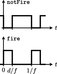
The output firing signal is strictly determined by the actual duty cycle, indicated as d in Fig. 1.
|
The firing signal is generated by comparing the sampled duty cycle input with a periodic saw tooth [Williams2006] or triangular signal (carrier).
Note
The user has the choice between two comparison modes:
commonComparison = true : The result of the comparison dutyCyle > carrier is fed to fire_p, the inverse signal to fire_n.
commonComparison = false: The result of the comparison dutyCyle > carrier is fed to fire_p, the result of the comparison (1 - dutyCyle) > carrier is fed to fire_n. (The result is the same for the comparison dutyCycle > (1 - carrier), i.e. a signal shifted by 180°.)
Parameters (6)
| useConstantDutyCycle |
Value: true Type: Boolean Description: Enables constant duty cycle |
|---|---|
| constantDutyCycle |
Value: 0 Type: Real Description: Constant duty cycle |
| f |
Value: 1000 Type: Frequency (Hz) Description: Switching frequency |
| refType |
Value: Modelica.Electrical.PowerConverters.Types.SingleReferenceType.Sawtooth Type: SingleReferenceType Description: Type of reference signal |
| commonComparison |
Value: true Type: Boolean Description: Common or separated comparison for fire_p and fire_n |
| startTime |
Value: 0 Type: Time (s) Description: Start time |
Connectors (3)
| dutyCycle |
Type: RealInput Description: Duty cycle |
|
|---|---|---|
| fire |
Type: BooleanOutput Description: Firing PWM signal |
|
| notFire |
Type: BooleanOutput Description: Firing PWM signal |
Components (10)
| const |
Type: Constant Description: Generate constant signal of type Real |
|
|---|---|---|
| limiter |
Type: Limiter Description: Limit the range of a signal |
|
| zeroOrderHold |
Type: ZeroOrderHold Description: Zero order hold of a sampled-data system |
|
| sawtooth |
Type: SawTooth Description: Generate saw tooth signal |
|
| triangle |
Type: Trapezoid Description: Generate trapezoidal signal of type Real |
|
| greaterEqual_p |
Type: Greater Description: Output y is true, if input u1 is greater than input u2 |
|
| inverse |
Type: Not Description: Logical 'not': y = not u |
|
| add |
Type: Add Description: Output the sum of the two inputs |
|
| constOne |
Type: Constant Description: Generate constant signal of type Real |
|
| greaterEqual_n |
Type: Greater Description: Output y is true, if input u1 is greater than input u2 |
Used in Examples (2)
|
Modelica.Electrical.PowerConverters.Examples.DCAC.PolyphaseTwoLevel Polyphase DC to AC converter with R load |
|
|
Modelica.Electrical.PowerConverters.Examples.DCAC.PolyphaseTwoLevel Polyphase DC to AC converter with R-L load |
Used in Components (6)
|
Modelica.Electrical.Machines.Examples.ControlledDCDrives.Utilities Switching DC-DC inverter |
|
|
Modelica.Electrical.PowerConverters.Examples.DCAC.ExampleTemplates Single-phase two level inverter including control |
|
|
Modelica.Electrical.PowerConverters.Examples.DCDC.ExampleTemplates Step down chopper including control |
|
|
Modelica.Electrical.PowerConverters.Examples.DCDC.ExampleTemplates Step up chopper including control |
|
|
Modelica.Electrical.PowerConverters.Examples.DCDC.ExampleTemplates Buck/boost converter example template |
|
|
Modelica.Electrical.PowerConverters.Examples.DCDC.ExampleTemplates H bridge DC/DC converter |