WOLFRAM SYSTEM MODELER
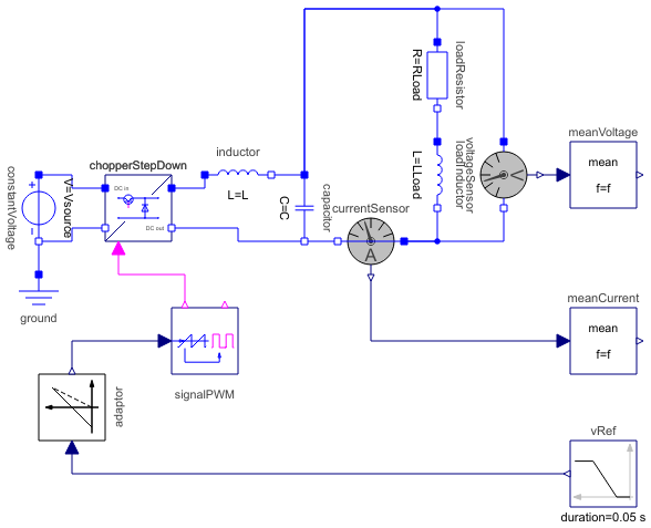
ChopperStepDown_RLStep down chopper with R-L load |
|
Diagram
Wolfram Language
In[1]:=
SystemModel["Modelica.Electrical.PowerConverters.Examples.DCDC.ChopperStepDown.ChopperStepDown_RL"]
Out[1]:=
Information
This information is part of the Modelica Standard Library maintained by the Modelica Association.
This example demonstrates the switching on of an R-L load operated by a step down chopper.
DC output voltage is equal to dutyCycle times the input voltage.
Plot current currentSensor.i, averaged current meanCurrent.y, total voltage voltageSensor.v and voltage meanVoltage.v. The waveform the average current is determined by the time constant L/R of the load.
Parameters (9)
| f |
Value: 1000 Type: Frequency (Hz) Description: Switching frequency |
|---|---|
| Vsource |
Value: 60 Type: Voltage (V) Description: Source voltage |
| L |
Value: 25e-3 Type: Inductance (H) Description: Source inductance |
| C |
Value: 20e-6 Type: Capacitance (F) Description: Smoothing capacitance |
| dutyCycle |
Value: 0.20 Type: Real Description: Duty cycle |
| ILoad |
Value: 1.2 Type: Current (A) Description: Load current |
| RLoad |
Value: V0 / ILoad Type: Resistance (Ω) Description: Load resistance |
| V0 |
Value: Vsource * dutyCycle Type: Voltage (V) Description: No-load output voltage |
| LLoad |
Value: 0.025 Type: Inductance (H) Description: Load inductance |
Components (14)
| constantVoltage |
Type: ConstantVoltage Description: Source for constant voltage |
|
|---|---|---|
| chopperStepDown |
Type: ChopperStepDown Description: Step down chopper |
|
| currentSensor |
Type: CurrentSensor Description: Sensor to measure the current in a branch |
|
| voltageSensor |
Type: VoltageSensor Description: Sensor to measure the voltage between two pins |
|
| ground |
Type: Ground Description: Ground node |
|
| signalPWM |
Type: SignalPWM Description: Generates a pulse width modulated (PWM) boolean fire signal |
|
| meanCurrent |
Type: Mean Description: Calculate mean over period 1/f |
|
| meanVoltage |
Type: Mean Description: Calculate mean over period 1/f |
|
| inductor |
Type: Inductor Description: Ideal linear electrical inductor |
|
| capacitor |
Type: Capacitor Description: Ideal linear electrical capacitor |
|
| loadResistor |
Type: Resistor Description: Ideal linear electrical resistor |
|
| loadInductor |
Type: Inductor Description: Ideal linear electrical inductor |
|
| adaptor |
Type: Voltage2DutyCycle Description: Linearly transforms voltage to duty cycle |
|
| vRef |
Type: Ramp Description: Generate ramp signal |