WOLFRAM SYSTEM MODELER
HBridge_RLH bridge DC/DC converter with R-L load |
|
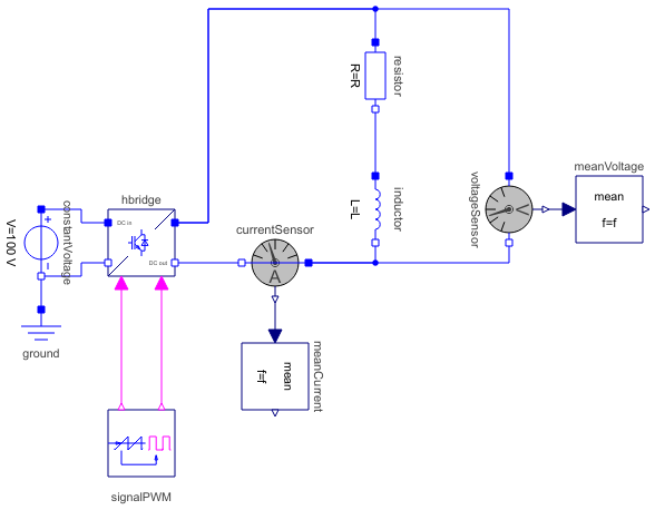
Diagram
Wolfram Language
In[1]:=
SystemModel["Modelica.Electrical.PowerConverters.Examples.DCDC.HBridge.HBridge_RL"]
Out[1]:=
Information
This information is part of the Modelica Standard Library maintained by the Modelica Association.
This example demonstrates the switching on of an R-L load operated by an H bridge.
DC output voltage is equal to 2 * (dutyCycle - 0.5) times the input voltage.
Plot current currentSensor.i, averaged current meanCurrent.y, total voltage voltageSensor.v and voltage meanVoltage.v. The waveform the average current is determined by the time constant L/R of the load.
Parameters (3)
| f |
Value: 1000 Type: Frequency (Hz) Description: Switching frequency |
|---|---|
| R |
Value: 100 Type: Resistance (Ω) Description: Resistance |
| L |
Value: 1 Type: Inductance (H) Description: Inductance |
Components (10)
| hbridge |
Type: HBridge Description: H bridge (four quadrant converter) |
|
|---|---|---|
| constantVoltage |
Type: ConstantVoltage Description: Source for constant voltage |
|
| signalPWM |
Type: SignalPWM Description: Generates a pulse width modulated (PWM) boolean fire signal |
|
| ground |
Type: Ground Description: Ground node |
|
| currentSensor |
Type: CurrentSensor Description: Sensor to measure the current in a branch |
|
| voltageSensor |
Type: VoltageSensor Description: Sensor to measure the voltage between two pins |
|
| meanCurrent |
Type: Mean Description: Calculate mean over period 1/f |
|
| meanVoltage |
Type: Mean Description: Calculate mean over period 1/f |
|
| resistor |
Type: Resistor Description: Ideal linear electrical resistor |
|
| inductor |
Type: Inductor Description: Ideal linear electrical inductor |