WOLFRAM SYSTEM MODELER
kc_evenGapTurbulent |
|
Wolfram Language
In[1]:=
SystemModel["Modelica.Fluid.Dissipation.Utilities.SharedDocumentation.HeatTransfer.Channel.kc_evenGapTurbulent"]
Out[1]:=
Information
This information is part of the Modelica Standard Library maintained by the Modelica Association.
Calculation of the mean convective heat transfer coefficient kc for a developed turbulent fluid flow through an even gap at heat transfer from both sides.
Functions kc_evenGapTurbulent and kc_evenGapTurbulent_KC
There are basically three differences:
- The function kc_evenGapTurbulent is using kc_evenGapTurbulent_KC but offers additional output variables like e.g. Reynolds number or Nusselt number and failure status (an output of 1 means that the function is not valid for the inputs).
- Generally the function kc_evenGapTurbulent_KC is numerically best used for the calculation of the mean convective heat transfer coefficient kc at known mass flow rate.
- You can perform an inverse calculation from kc_evenGapTurbulent_KC, where an unknown mass flow rate is calculated out of a given mean convective heat transfer coefficient kc
Restriction
- identical and constant wall temperatures
- hydraulic diameter per gap length (d_hyd / L) ≤ 1
- 0.5 ≤ Prandtl number Pr ≤ 100)
- turbulent regime (3e4 ≤ Reynolds number ≤ 1e6)
- developed fluid flow
- heat transfer from both sides of the gap (target = Modelica.Fluid.Dissipation.Utilities.Types.kc_evenGap.DevBoth)
Geometry
Calculation
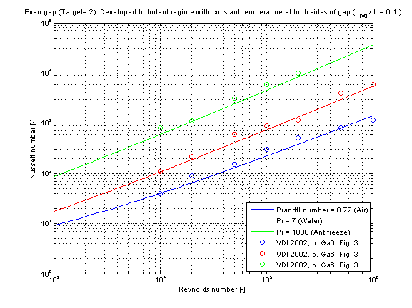
The mean convective heat transfer coefficient kc for an even gap is calculated through the corresponding Nusselt number Nu_turb according to Gnielinski in [VDI 2002, p. Gb 7, sec. 2.4]
Nu_turb =(zeta/8)*Re*Pr/{1+12.7*[zeta/8]^(0.5)*[Pr^(2/3) -1]}*{1+[d_hyd/L]^(2/3)}
where the pressure loss coefficient zeta according to Konakov in [VDI 2002, p. Ga 5, eq. 27] is determined by
zeta = 1/[1.8*log10(Re) - 1.5]^2
resulting to the corresponding mean convective heat transfer coefficient kc
kc = Nu_turb * lambda / d_hyd
with
| cp | as specific heat capacity at constant pressure [J/(kg.K)], |
| d_hyd = 2*s | as hydraulic diameter of gap [m], |
| eta | as dynamic viscosity of fluid [Pa.s], |
| h | as height of cross sectional area in gap [m], |
| kc | as mean convective heat transfer coefficient [W/(m2.K)], |
| lambda | as heat conductivity of fluid [W/(m.K)], |
| L | as overflowed length of gap (normal to cross sectional area) [m] , |
| Nu_turb | as mean Nusselt number for turbulent regime [-], |
| Pr = eta*cp/lambda | as Prandtl number [-], |
| rho | as fluid density [kg/m3], |
| s | as distance between parallel plates of cross sectional area [m], |
| Re = rho*v*d_hyd/eta | as Reynolds number [-], |
| v | as mean velocity in gap [m/s], |
| zeta | as pressure loss coefficient [-]. |
Note that the fluid flow properties shall be calculated with an arithmetic mean temperature out of the fluid flow temperatures at the entrance and the exit of the gap.
Verification
The mean Nusselt number Nu_turb representing the mean convective heat transfer coefficient kc in dependence of the chosen fluid flow and heat transfer situations (targets) is shown in the figure below.
- Target 2: Developed fluid flow and heat transfer from both sides of the gap
References
- VDI:
- VDI - Wärmeatlas: Berechnungsblätter für den Wärmeübergang. Springer Verlag, 9th edition, 2002.