WOLFRAM SYSTEM MODELER
dp_overall |
|
Wolfram Language

SystemModel["Modelica.Fluid.Dissipation.Utilities.SharedDocumentation.PressureLoss.StraightPipe.dp_overall"]
Information
This information is part of the Modelica Standard Library maintained by the Modelica Association.
Calculation of pressure loss in a straight pipe for laminar or turbulent flow regime of single-phase fluid flow only considering surface roughness.
Restriction
This function shall be used within the restricted limits according to the referenced literature.
- circular cross sectional area
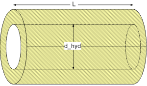
Geometry
Calculation
The pressure loss dp for straight pipes is determined by:dp = lambda_FRI * (L/d_hyd) * (rho/2) * velocity^2
with
| lambda_FRI | as Darcy friction factor [-], |
| L | as length of straight pipe [m], |
| d_hyd | as hydraulic diameter of straight pipe [m], |
| rho | as density of fluid [kg/m3], |
| velocity | as mean velocity [m/s]. |
The Darcy friction factor lambda_FRI for straight pipes is calculated depending on the fluid flow regime (with corresponding Reynolds number Re) and the absolute surface roughness K.
The Laminar regime is calculated for Re ≤ 2000 by the Hagen-Poiseuille law according to [Idelchik 2006, p. 77, eq. 2-3]
lambda_FRI = 64/Re
The Darcy friction factor lambda_FRI in the laminar regime is independent of the surface roughness k as long as the relative roughness k is smaller than 0.007. A greater relative roughness k than 0.007 is leading to an earlier leaving of the Hagen-Poiseuille law at some value of Reynolds number Re_lam_leave. The leaving of the laminar regime in dependence of the relative roughness k is calculated according to [Samoilenko in Idelchik 2006, p. 81, sect. 2-1-21] as:
Re_lam_leave = 754*exp(if k ≤ 0.007 then 0.93 else 0.0065/k)
The Transition regime is calculated for 2000 < Re ≤ 4000 by a cubic interpolation between the equations of the laminar and turbulent flow regime. Different cubic interpolation equations for the calculation of either pressure loss dp or mass flow rate m_flow results in a deviation of the Darcy friction factor lambda_FRI through the transition regime. This deviation can be neglected due to the uncertainty in determination of the fluid flow in the transition regime.
Turbulent regime can be calculated for a smooth surface (Blasius law) or a rough surface (Colebrook-White law):
Smooth surface (roughness = Modelica.Fluid.Dissipation.Utilities.Types.Roughness.Neglected) w.r.t. Blasius law in the turbulent regime according to [Idelchik 2006, p. 77, sec. 15]:
lambda_FRI = 0.3164*Re^(-0.25)
with
| lambda_FRI | as Darcy friction factor [-]. |
| Re | as Reynolds number [-]. |
Note that the Darcy friction factor lambda_FRI for smooth straight pipes in the turbulent regime is independent of the surface roughness K .
Rough surface (roughness = Modelica.Fluid.Dissipation.Utilities.Types.Roughness.Considered) w.r.t. Colebrook-White law in the turbulent regime according to [Miller 1984, p. 191, eq. 8.4]:
lambda_FRI = 0.25/{lg[k/(3.7*d_hyd) + 5.74/(Re)^0.9]}^2
with
| d_hyd | as hydraulic diameter [-], |
| k= K/d_hyd | as relative roughness [-], |
| K | as roughness (average height of surface asperities [m], |
| lambda_FRI | as Darcy friction factor [-], |
| Re | as Reynolds number [-]. |
Verification
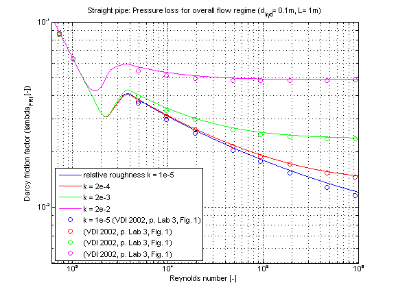
The Darcy friction factor lambda_FRI in dependence of Reynolds number for different values of relative roughness k is shown in the figure below.
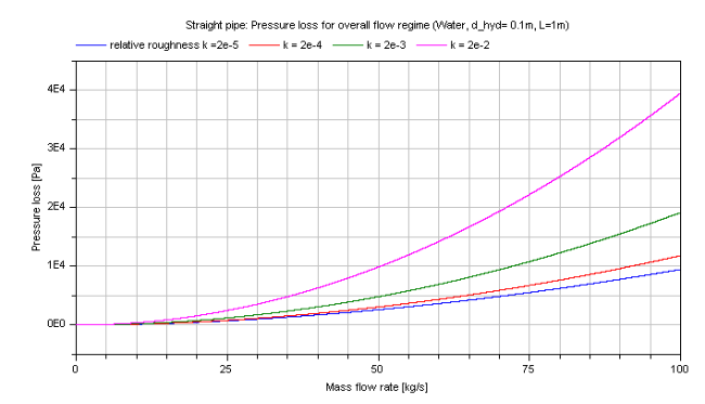
The pressure loss dp for the turbulent regime in dependence of the mass flow rate of water is shown in the figure below.
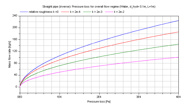
And the mass flow rate m_flow for the turbulent regime in dependence of the pressure loss of water is shown in the figure below.
References
- Idelchik,I.E.:
- Handbook of hydraulic resistance. Jaico Publishing House, Mumbai, 3rd edition, 2006.
- Miller,D.S.:
- Internal flow systems. volume 5th of BHRA Fluid Engineering Series.BHRA Fluid Engineering, 1984.
- Samoilenko,L.A.:
- Investigation of the hydraulic resistance of pipelines in the zone of transition from laminar into turbulent motion. PhD thesis, Leningrad State University, 1968.
- VDI:
- VDI - Wärmeatlas: Berechnungsblätter für den Wärmeübergang. Springer Verlag, 9th edition, 2002.
