WOLFRAM SYSTEM MODELER
ToroidalCoreAirgapEducational example: iron core with airgap |
|
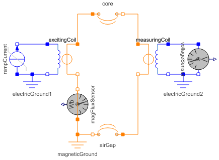
Diagram
Wolfram Language
In[1]:=
SystemModel["Modelica.Magnetic.FluxTubes.Examples.BasicExamples.ToroidalCoreAirgap"]
Out[1]:=
Information
This information is part of the Modelica Standard Library maintained by the Modelica Association.
Educational example of a magnetic circuit containing a toroidal iron core with circular cross section and an airgap:
A current ramp is applied in positive electric direction through the exciting coil, causing a rising magnetomotive force (mmf) in positive magnetic direction of the electromagnetic converter. The mmf in turn causes a magnetic flux through the circuit in the direction indicated by the flux sensor. From that magnetic flux, flux density can be calculated in every element of the magnetic circuit. Flux density is used to derive magnetic field strength. Magnetic field strength times length of the flux line gives magnetic potential difference of each element. The sum of all magnetic potential differences is covered by the mmf of the exciting coil.
Using the values shown in section Parameters, the results can be validated easily by analytic calculations:
| element | cross section | length | rel. permeability | B | H | mmf |
|---|---|---|---|---|---|---|
| core | d2*pi/4 | r*alpha | μr | flux / cross section | B/(μr*μ0) | H*length |
| airgap | d2*pi/4 | delta=r*(2*pi-alpha) | 1 | flux / cross section | B/(μ0) | H*delta |
| total | Σ mmf = N*I |
Note that since no leakage is present, the magnetic flux is the same in every element - they are connected in series. For calculation of the length of flux lines, a flux line in the middle of the toroid is used.
Additionally, a measuring coil is placed in the airgap. Due to Faraday's law, the time derivative of flux causes an induced voltage both in the exciting coil (in positive direction) and in the measuring coil (in negative direction). Since current is given as a linear-time dependent ramp, the induced voltages during that ramp are constant and otherwise zero. Note that usage of nonlinear magnetic material would change that result due the nonlinear relationship between magnetic field strength and flux density.
Note the proper usage of electric and magnetic grounds to define zero potential.
Parameters (7)
| r |
Value: 0.05 Type: Length (m) Description: Middle radius of iron core |
|---|---|
| d |
Value: 0.01 Type: Length (m) Description: Diameter of cylindrical cross section |
| mu_r |
Value: 1000 Type: RelativePermeability Description: Relative permeability of core |
| delta |
Value: 0.001 Type: Length (m) Description: Length of airgap |
| alpha |
Value: (1 - delta / (2 * pi * r)) * 2 * pi Type: Angle (rad) Description: Section angle of toroidal core |
| N |
Value: 500 Type: Integer Description: Number of exciting coil turns |
| I |
Value: 1.5 Type: Current (A) Description: Maximum exciting current |
Components (10)
| excitingCoil |
Type: ElectroMagneticConverter Description: Ideal electromagnetic energy conversion |
|
|---|---|---|
| core |
Type: Toroid Description: Toroid with circular cross section; fixed shape; linear or non-linear material characteristics |
|
| airGap |
Type: Toroid Description: Toroid with circular cross section; fixed shape; linear or non-linear material characteristics |
|
| measuringCoil |
Type: ElectroMagneticConverter Description: Ideal electromagnetic energy conversion |
|
| magneticGround |
Type: Ground Description: Zero magnetic potential |
|
| electricGround1 |
Type: Ground Description: Ground node |
|
| rampCurrent |
Type: RampCurrent Description: Ramp current source |
|
| magFluxSensor |
Type: MagneticFluxSensor Description: Sensor to measure magnetic flux |
|
| electricGround2 |
Type: Ground Description: Ground node |
|
| voltageSensor |
Type: VoltageSensor Description: Sensor to measure the voltage between two pins |