WOLFRAM SYSTEM MODELER
ComparisonPullInStrokePull-in stroke of both solenoid models after a voltage step at time t=0 |
|
Diagram
Wolfram Language
In[1]:=
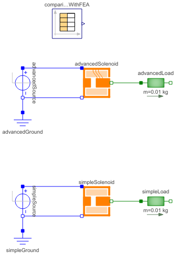
SystemModel["Modelica.Magnetic.FluxTubes.Examples.SolenoidActuator.ComparisonPullInStroke"]
Out[1]:=
Information
This information is part of the Modelica Standard Library maintained by the Modelica Association.
Have a look at SolenoidActuator for general comments and at SimpleSolenoid and AdvancedSolenoid for a detailed description of both magnetic network models.
A voltage step is applied to both solenoid models at time t=0. The armatures of both models and therewith connected loads are pulled from their rest position at maximum air gap length to their minimum position that is due to a stopper. As a reference, simulation results obtained with a dynamic model based on stationary FEA look-up tables (not part of this library) are included. Note that these reference results are valid for the default supply voltage v_step=12V DC and the default load mass m_load=0.01kg only!
Set the tolerance to 1e-7 and simulate for 0.05 s. Plot actuator current, force and position of the two magnetic network models and the FEA-based reference vs. time (each quantity in one common plot window):
Plot window for current:
    simpleSolenoid.p.i          // rapid current rise indicates low inductance of simple network model
    advancedSolenoid.p.i        // current rise slower, better match with FEA reference
    comparisonWithFEA.y[1]      // current obtained from dynamic model based on stationary FEA look-up tables

Plot window for force:
    simpleSolenoid.armature.flange_a.f       // reluctance force of simple actuator model
    advancedSolenoid.armature.flange_a.f     // reluctance force of advanced actuator model
    comparisonWithFEA.y[2]      // force obtained from dynamic model based on stationary FEA look-up tables

Plot window for position:
    simpleSolenoid.x            // armature position of simple actuator model
    advancedSolenoid.x          // armature position of advanced actuator model
    comparisonWithFEA.y[3]      // position obtained from dynamic model based on stationary FEA look-up tables
The characteristic current drop during pull-in is due to both armature motion and increasing inductance with decreasing air gap length. Bouncing occurs when armature and load of each model arrive at the stopper at minimum position. Although the pull-in times of the two magnetic network models are relatively close to the time obtained with the reference model, the accuracy of the advanced solenoid model is better, as one can tell from a comparison of the current rise at the beginning of the stroke.
Parameters (1)
| v_step |
Value: 12 Type: Voltage (V) Description: Applied voltage |
|---|
Components (9)
| advancedGround |
Type: Ground Description: Ground node |
|
|---|---|---|
| advancedSource |
Type: StepVoltage Description: Step voltage source |
|
| advancedSolenoid |
Type: AdvancedSolenoid Description: Advanced network model of a lifting magnet with planar armature end face, split magnetomotive force |
|
| advancedLoad |
Type: Mass Description: Translatory load to be pulled horizontally |
|
| simpleGround |
Type: Ground Description: Ground node |
|
| simpleSource |
Type: StepVoltage Description: Step voltage source |
|
| simpleSolenoid |
Type: SimpleSolenoid Description: Simple network model of a lifting magnet with planar armature end face |
|
| simpleLoad |
Type: Mass Description: Translatory load to be pulled horizontally |
|
| comparisonWithFEA |
Type: CombiTimeTable Description: Valid for u_source=12VDC and m_load=0.01kg only; column 2: current, col.3: force, col.4: position |