WOLFRAM SYSTEM MODELER
EngineThrottleControl |
|
Diagram
Wolfram Language
In[1]:=
SystemModel["Modelica_Synchronous.Examples.Systems.EngineThrottleControl"]
Out[1]:=
Information
This example shows how to model a non-periodic synchronous sampled data systems
with the Modelica_Synchronous library. This is demonstrated at hand
of a closed-loop throttle control synchronized to the crankshaft angle of an
internal combustion engine. This system has the following properties:
- Engine speed is regulated with a throttle actuator.
- Controller execution is synchronized with the engine crankshaft angle.
- The influence of disturbances, such as a change in load torque, is reduced.
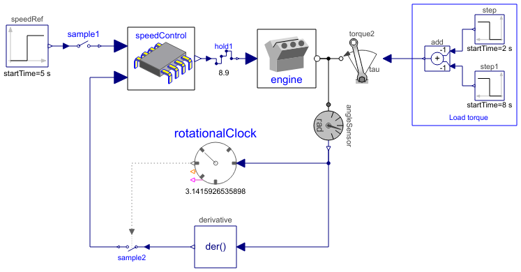
The complete system is shown in figure below (diagram-layer):
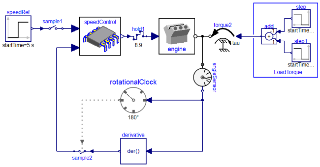
Block speedControl is the discrete control system. The boundaries
of this controller are defined by sample1, sample2 and
hold1. The sampling is done via rotationalClock, an
event-based clock that ticks every 180° rotation of the crankshaft angle. The
speed controller therefore is automatically executed every half-rotation of the
engine's crankshaft. To produce respective clock ticks,
rotationalClock
bookeeps the angular of the last time a half-rotation of
the crankshaft has been recognized (angular_offset). Given
angular_offset, the event-condition for half-rotations is:
abs(angle - angular_offset) >= abs(trigger_interval)
with trigger_interval = 180°. The model of
rotationalClock therefore is (diagram-layer):
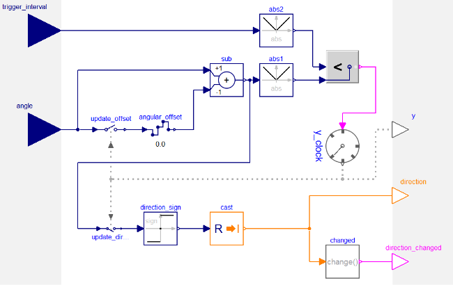
In the end, rotationalClock samples it's own input angle to bookeep
an offset used to decide when to tick; the clock's event condition depends on
the state present when the condition changed last time from beeing non-satisfied
to beeing satisfied, i.e., the state when the clock last ticked.
Components (13)
| speedRef |
Type: Step Description: Generate step signal of type Real |
|
|---|---|---|
| speedControl |
Type: SpeedControl Description: Discrete control of crankshaft speed by throttle actuation |
|
| sample1 |
Type: Sample Description: Sample the continuous-time, Real input signal and provide it as clocked output signal (clock is inferred) |
|
| hold1 |
Type: Hold Description: Hold the clocked, Real input signal and provide it as continuous-time output signal (zero order hold) |
|
| rotationalClock |
Type: FixedRotationalClock Description: Event clock generating a clock tick each time an observed input angle changed for a certain, constant rotational-interval. |
|
| engine |
Type: Engine2 Description: Internal combustion engine |
|
| step |
Type: Step Description: Generate step signal of type Real |
|
| step1 |
Type: Step Description: Generate step signal of type Real |
|
| add |
Type: Add Description: Output the sum of the two inputs |
|
| torque2 |
Type: Torque Description: Input signal acting as external torque on a flange |
|
| angleSensor |
Type: AngleSensor Description: Ideal sensor to measure the absolute flange angle |
|
| derivative |
Type: Der Description: Derivative of input (= analytic differentiations) |
|
| sample2 |
Type: SampleClocked Description: Sample the continuous-time, Real input signal and provide it as clocked output signal. The clock is provided as input signal |