


CreateSystemModel
CreateSystemModel[sys]
creates a Modelica SystemModel from the systems model sys.
CreateSystemModel[eqns,t]
creates a model for the system equations eqns with independent variable t.
CreateSystemModel[…,tspec]
creates a model with type specification tspec for variables and parameters.
CreateSystemModel[…,spec]
creates a model with spec for parameter values, initial values and model relations.
Details and Options
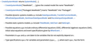


- CreateSystemModel returns SystemModel[…].
- CreateSystemModel["NewModel",…] gives the created model the name "NewModel".
- CreateSystemModel["PackageA.NewModel"] inserts "NewModel" into "PackageA".
- Possible dynamic systems models sys include StateSpaceModel, TransferFunctionModel, AffineStateSpaceModel, NonlinearStateSpaceModel and DiscreteInputOutputModel. »
- Possible static systems models sys include FittedModel, NetChain and NetGraph.
- Possible equations eqns include ordinary differential equations (ODE), differential algebraic equations (DAE), initial value equations and event specifications given by WhenEvent. »
- Parameters in eqns and sys are taken to be variables that do not explicitly depend on t.
- Type specifications tspecs for variables and parameters {tspec1,…}, where each tspeci has the form:
-
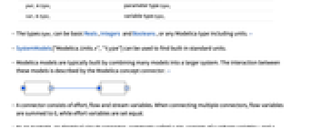
pari∈typei parameter type typei vari∈typei variable type typei - The types typei can be basic Reals, Integers and Booleans, or any Modelica type including units. »
- SystemModels["Modelica.Units.*","type"] can be used to find built-in standard units.
- Modelica models are typically built by combining many models into a larger system. The interaction between these models is described by the Modelica concept connector. »
- A connector consists of effort, flow and stream variables. When connecting multiple connectors, flow variables are summed to 0, while effort variables are set equal.
- As an example, an electrical circuit connector, commonly called a pin, consists of a voltage variable v and a current variable i.
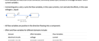
- Connecting pins n and p sums the flow variables, in this case currents i, to 0 and sets the efforts, in this case voltages v, equal:
- All flow variables are positive in the direction flowing into a component.
- Effort and flow variables for different domains include:
-
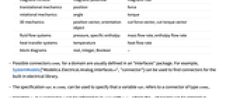
Domain Effort Variables Flow Variables electrical circuits voltage current magnetic circuits magnetic potential magnetic flux translational mechanics position force rotational mechanics angle torque 3D mechanics position vector, orientation object cut force vector, cut torque vector fluid flow systems pressure, specific enthalpy mass flow rate, enthalpy flow rate heat transfer systems temperature heat flow rate block diagrams real, integer, Boolean - - Possible connectors conni for a domain are usually defined in an Interfaces package. For example, SystemModels["Modelica.Electrical.Analog.Interfaces.*","connector"] can be used to find connectors for the built-in electrical library.
- The specification vari∈conni can be used to specify that a variable vari refers to a connector of type conni.
- Variables vi in a connector c can be referred to in eqns with c▴vi, where the ▴ character can be entered as \[UpPointer].
- The variables defined by a connector conn can be listed with SystemModel[conn,"SystemVariables"].
- In CreateSystemModel[…,spec], spec is an Association with the following keys:
-
"ParameterValues" {p1val1,…} parameter values "InitialValues" {v1val1,…} initial values "ExtendsModels" {partial1,…} partial models to build on "DiscreteVariables" {v1,v2,…} variables changing only at events "SimulationSettings" {opt1val1,…} model simulation options - Libraries often contain partial models called interfaces for building new component models. These interfaces usually consist of connectors and equations describing the basic relationships between them.
- With CreateSystemModel[…,"ExtendsModels"partial], the new model is combined with the existing partial SystemModel defined in Modelica. »
- A model can extend multiple models using "ExtendsModels"{"partial1",…}.
- Partial models to build on are usually defined in an Interfaces package. For example, SystemModels["Modelica.Electrical.Analog.Interfaces.*","model""block"] can be used to find partial models for the built-in electrical library.
- "InitialValues" correspond to the start property in the Modelica model.
- Allowed options in "SimulationsSettings"->{opt1val1,…} include:
-
"Method" simulation method "StartTime" simulation start time "StopTime" simulation stop time - Available adaptive step "Method" values include:
-
"DASSL" DASSL DAE solver "CVODES" CVODES ODE solver - Options for adaptive-step methods include:
-
"InterpolationPoints" number of interpolation points "Tolerance" tolerance for adaptive step size - Available fixed-step "Method" values include:
-
"Euler" explicit Euler's method of order 1 "Heun" Heun's method of order 2 "RungeKutta" explicit Runge–Kutta method of order 4 - Options for fixed-step methods include:
-
"StepSize" fixed step size - With the option GeneratedAssetLocationloc, you can store generated assets in location loc.
Examples
open all close allBasic Examples (3)
Create a model based on a StateSpaceModel:
Create a model based on a TransferFunctionModel, giving it a custom name:
Scope (50)
Systems Models (11)
Create a model of a single-input, single-output TransferFunctionModel:
Create a model of a single-input, single-output StateSpaceModel:
Multiple input, multiple output:
Create a model with parameters in a transfer-function model:
Specify parameters in a state-space model:
Define parameter values in a transfer-function model:
Give parameter values in a state-space model:
Give the types and values of parameters:
Create a model from a discrete transfer-function model:
Create a model from a discrete state-space model:
Create a model from an affine state-space model:
Differential Equations (12)
Create a single-equation ODE system:
Specify any order equation. Reduction of higher-order derivatives is done automatically:
Define a system of multiple equations:
Define a system with an algebraic constraint, resulting in a high-index problem:
Hybrid equations can be specified using WhenEvent:
Declare a variable a that only changes at discrete times:
Simulate and plot the model of a bouncing ball on stairs:
Wolfram Language functions are automatically translated to their Modelica equivalent:
Specify a default parameter value:
Specify types for variables and parameters:
Arrays are expressed using Indexed:
Functions used in equations are translated into functions in Modelica:
Associations and Functions (4)
An Association is converted into a record:
Use a record to store the kinematics of a particle:
Create a class with a specialization function from a Function:
Use a Module to introduce protected variables:
Regions and Graphics3D (2)
Regions with an embedding dimension of 3 produce objects with visualization and dynamical properties:
Data like RegionMeasure, RegionCentroid and MomentOfInertia is stored using "Modelica.Mechanics.MultiBody" components:
Graphics3D objects are exported to produce visualizations:
DiscretizeGraphics or BoundaryDiscretizeGraphics may be able to produce a region from a Graphics3D:
Fitted Models and Neural Networks (2)
Create an input-output block from a FittedModel:
Give an input, simulate and plot:
Create an input-output block from a trained or initialized NetChain or NetGraph:
Naming Models (3)
Types and Connectors (4)
Initial and Parameter Values (6)
Build on Partial Models (3)
Options (2)
GeneratedAssetLocation (2)
Models created from regions export an asset file to $WolframDocumentsDirectory by default:
Specify a location for assets using GeneratedAssetLocation:
Models created from neural networks export an ONNX file to $WolframDocumentsDirectory by default:
Specify a location for assets using GeneratedAssetLocation:
Applications (7)
Define the equations for a bouncing ball:
Simulate with a restitution of 95%:
Create a model of the Lotka–Volterra equations, modeling a predator-prey relationship:
Define initial values for the two states:
Show the levels of predators and prey over time:
A higher prey growth parameter speeds up the cycles in the system:
Model two connected tanks with a leak in the second tank:
Set up the equations, which include initial equations and parameters:
Create the model, using a given set of parameter values as the default:
Both tanks drain over time, because the second tank is leaking:
Create a mechanical translational damper with damping in only one direction:
Create the damper using a partial interface from the Translational Mechanics library:
Compare with a bidirectional damper:
Create a digital lowpass filter:
Convert the filter into a transfer function:
Create a signal generating source:
Connect the signal source to the filter:
Simulate and plot the signal output and the filtered signal:
Use a region together with a world component to create a new model in which the body is affected by gravity:
Simulate and plot the position of the center of mass:
Visualize rotational phenomena for a parallelepiped:
Turn off gravity by changing a parameter in the world component and give an initial value to the angular velocity:
Simulate and obtain the rotation matrix of the frame fixed to the body:
Properties & Relations (3)
SystemModel properties can be used to extract information from a model:
Create a new model with equations from an existing model, changing a parameter:
Simulate and compare the two models:
Special characters are translated into their long form:
Subscript is translated into _:
Possible Issues (2)
Models are not saved unless explicitly saved:
After quitting the Wolfram Language kernel, the model is gone:
CreateSystemModel supports a subset of Wolfram Language functions:
Related Links
Text
Wolfram Research (2018), CreateSystemModel, Wolfram Language function, https://reference.wolfram.com/language/ref/CreateSystemModel.html (updated 2022).
CMS
Wolfram Language. 2018. "CreateSystemModel." Wolfram Language & System Documentation Center. Wolfram Research. Last Modified 2022. https://reference.wolfram.com/language/ref/CreateSystemModel.html.
APA
Wolfram Language. (2018). CreateSystemModel. Wolfram Language & System Documentation Center. Retrieved from https://reference.wolfram.com/language/ref/CreateSystemModel.html