|
1. Getting Started OverviewThis chapter is intended to familiarize the user with MechanicalSystems and to provide an overview of its basic functionality. MechanicalSystems actually consists of two basic Mathematica packages; one for planar mechanisms, Modeler2D, and one for spatial mechanisms, Modeler3D. Throughout this manual, the planar and spatial components of MechanicalSystems are often referred to by their package names, Modeler2D and Modeler3D, and the entire MechanicalSystems package is simply referred to as Mech.
Section 1.1 describes the steps necessary to load MechanicalSystems into a Mathematica session on various computer systems. In Sections 1.2 and 1.3 two very basic kinematic models (one planar and one spatial) are developed to demonstrate the general functionality of Mech. Both models are of a slider-crank mechanism, such as a small internal combustion engine, and they are presented with minimal explanation. The two models are essentially identical to show the parallelism between Modeler2D and Modeler3D. Further exploration of the functions introduced in this chapter and all of the other functions provided for kinematic modeling can be found in Chapter 2. 1.1 Starting MechanicalSystemsThis section covers the loading of MechanicalSystems packages into a Mathematica session on various computer systems. 1.1.1 Main PackageThe MechanicalSystems packages are loaded into Mathematica in the same manner as a standard Mathematica package; with a Get or Needs statement. Loading the Mech packages. This loads the Modeler2D package. It is not possible to have both Modeler2D and Modeler3D loaded simultaneously because they use many of the same function names with different definitions. Attempting to load Modeler3D while Modeler2D is already loaded results in Modeler2D being unloaded and replaced with Modeler3D - and vice versa.
The MechanicalSystems packages are not intended to be loaded twice. Thus, it is recommended that Needs be used to load the packages because Needs will not read the package if it has already been read. If Get is accidentally used to load one of the Mech packages after it has already been loaded, an error message is generated, and the Get operation is aborted. 1.1.2 Secondary PackagesThe MechanicalSystems secondary packages Dynamics2D/3D, Graphics2D/3D, and Utilities2D/3D need not be loaded explicitly. They are loaded automatically if any of the function definitions they contain are needed. However, if the Information or Definition functions are to work correctly with the functions in the secondary packages, these packages must be loaded into Mathematica. Note that requesting information about a MechanicalSystems function with ?functioname will not cause the associated packages to be autoloaded. This causes all of the Modeler2D packages to be loaded, including Modeler2D itself. 1.1.3 Clearing and UnloadingMechanicalSystems may be reset to its initial state, or removed entirely from the current Mathematica session without quitting and restarting Mathematica, with the ClearMech or KillMech functions. Resetting or removing Mech. This removes the entire Modeler2D or Modeler3D package. After executing KillMech nothing remains of the Mech session except whatever definitions the user had made in the Global` context, and a few undefined symbols that Mech creates in the Global` context. The Mech packages can be reloaded with Get or Needs after executing KillMech. 1.2 Basic 2D ModelIn this section the basic functionality of the Modeler2D package is demonstrated by building a kinematic model of a very simple mechanism. The mechanism is a planar slider-crank mechanism with two moving bodies, the crankshaft and the piston. The mechanism is modeled using the most abbreviated technique possible with Modeler2D. Later chapters will delve into the many more complex variations on these techniques. 1.2.1 Mechanism FunctionThe Modeler2D package must be loaded before calling any Mech functions. This loads Modeler2D. Here is a graphic of the 2D slider-crank model.
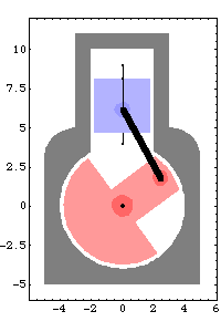
The following example analyzes the motion of a classic slider-crank mechanism. This mechanism is modeled with a simple and intuitive set of mechanical constraints that are representative of how such a problem would usually be modeled. Body NumbersThe slider-crank mechanism consists of three bodies.
Body 1 is the ground body.
Body 2 is the crankshaft.
Body 3 is the piston.Each independent body in a Mech model must be given a unique positive integer body number. The choice of each body number is arbitrary, except for the ground body, which must be body 1. These body numbers are used throughout a Mech model to reference each body. The ground body, which is stationary by definition, is used as the reference location and orientation for the rest of the model. All mechanism models must have some reference to the ground body to be adequately constrained.
To aid in the readability of the mechanism models created with Mech, a good practice is to name each of the bodies in a mechanism, and then define each of these names to be equal to the integer body number of the body. Each body can then be referenced by name instead of by a number. Body names are defined to be used as references for each body. A real slider-crank mechanism would have a fourth body, the connecting rod between the crankshaft and the piston. However, in the kinematic model this entire part can be replaced by a simple distance constraint specifying that the crank pin and the piston pin are a constant distance apart. This technique decreases the overall size of the model. Local CoordinatesEach body in a mechanism model must have a local coordinate system attached to it. How to place this coordinate system on the body is up to the user and is based on the needs of the model. It is not necessary to place the local coordinate origin at the center of gravity of the body. The local coordinate system of each body is used to define points, lines, and other features on the body that are then tied together to make the mechanical constraints.
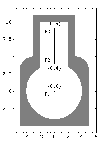
The local coordinate system of body 1, the ground body, is always coincident with the global coordinate system. Therefore, the global coordinate system is referenced through the ground body, simply by specifying body 1. 1.2.2 2D BodiesGroundThe local coordinate system of the ground body originates at the rotational center of the crankshaft. Three points are used on the ground body.
P1 is a point at the global origin that is the rotational axis of the crankshaft.
P2 and P3 are two points that define the vertical line upon which the piston translates.Here is a graphic of the ground body.
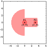
CrankshaftThe local coordinate system of the crankshaft originates at its rotational center. Two points are used on the crankshaft.
P1 is a point at the local origin that is the rotational axis of the crankshaft.
P2 is a point on the local x axis that is the attachment point of the connecting rod.Here is a graphic of the crankshaft.
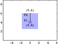
PistonThe local coordinate system of the piston originates four units below the attachment point of the connecting rod. Thus, when the mechanism is in its initial configuration, the local origin of the piston is coincident with the global origin. Two points are used on the piston.
P1 is the attachment point of the connecting rod.
P2 is used with P1 to define the vertical translation line of the piston.Here is a graphic of the piston.
1.2.3 2D ConstraintsNow that the local point coordinates on each body are defined, building the model is simply a matter of tying the points together with the correct mechanical constraints. Modeler2D provides a small library of mechanical constraint objects that translate desired physical conditions that are imposed on the model into mathematical equations. Constraint ObjectsFour constraint objects are used to model the slider-crank mechanism, constraining a total of six degrees of freedom (three degrees of freedom for each moving body). Some 2D constraint objects. Note that the last character in the name of any Mech constraint object is an integer that specifies the number of degrees of freedom that it constrains.
The first argument to each constraint object, cnum, is the user-specified constraint number. This number is used to reference the constraint later in the modeling process, much like body numbers are used to reference specific bodies.
The point and axis arguments of Modeler2D constraint objects are specified with Point, Line, or Axis objects, used in much the same manner as the built-in Mathematica graphics primitives Point and Line. These objects are discussed in detail in Section 2.2. Building the ModelThe Modeler2D constraint objects used to model the physical relationships in the slider-crank mechanism are as follows. A Revolute2 constraint forces the axis of the crankshaft to be coincident with the global origin. This constrains the X and Y displacement of the crankshaft axis. The one degree of freedom left for the crankshaft is its rotation about its axis. The syntax of the constraint can be interpreted as, "Constrain a point at  on the ground body to be coincident with point on the ground body to be coincident with point  on the crankshaft."A RotationLock1 constraint specifies the angular coordinate of the crankshaft. The crankshaft is now completely constrained. The syntax of this constraint can be interpreted as, "Constrain the angular coordinate of the crankshaft to be equal to crankangle."A Translate2 constraint forces a vertical line on the piston to be coincident with a vertical line on the ground body. This constrains two degrees of freedom, horizontal translation and rotation of the piston. The one degree of freedom left is the vertical translation of the piston relative to the ground.A RelativeDistance1 constraint forces an eccentric point on the crankshaft to lie five units distant from the origin of the piston. This single constraint takes the place of a connecting rod five units long. Since the crankshaft is already completely constrained, this completes the constraint of the piston. on the crankshaft."A RotationLock1 constraint specifies the angular coordinate of the crankshaft. The crankshaft is now completely constrained. The syntax of this constraint can be interpreted as, "Constrain the angular coordinate of the crankshaft to be equal to crankangle."A Translate2 constraint forces a vertical line on the piston to be coincident with a vertical line on the ground body. This constrains two degrees of freedom, horizontal translation and rotation of the piston. The one degree of freedom left is the vertical translation of the piston relative to the ground.A RelativeDistance1 constraint forces an eccentric point on the crankshaft to lie five units distant from the origin of the piston. This single constraint takes the place of a connecting rod five units long. Since the crankshaft is already completely constrained, this completes the constraint of the piston.The Modeler2D constraint objects are finally assembled into a mechanism model with SetConstraints. The fundamental model-building function. Here is the entire slider-crank model built in one step. SetConstraints returns nothing upon success. All of the constraint equations generated by SetConstraints are stored internally in the Modeler2D private context. 1.2.4 Running the ModelA single command is used to solve the constraint equations and return a list of rules representing the coordinates of each body in the model. The fundamental model-solving function. This seeks a solution at crankangle = 0.
Out[8]= |  |
SolveMech returns the global coordinates of the origin of each body in the system. The symbols X2 and Y2 specify the location of the origin of body 2, the crankshaft, and  2 specifies the rotation of the crankshaft. SolveMech returns a 2 specifies the rotation of the crankshaft. SolveMech returns a  triplet for each body in the system. triplet for each body in the system. A graphic of the model at crankangle = 0.
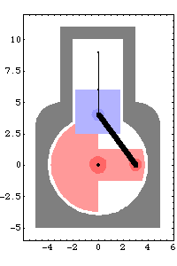
Big surprise! The trivial solution at crankangle = 0 corresponds to the local coordinate system of each body being aligned with the global coordinate system. This is because the model was defined such as to have this perfect assembled configuration. The piston is defined such that its local origin lies at a point that is outside of the piston body, directly on the global origin when crankangle = 0. Note also the 3-4-5 triangle formed by the crankshaft, piston, and connecting rod when crankangle = 0.
Advancing crankangle results in a more interesting solution. This seeks a solution at crankangle = 1/10 revolution.
Out[10]= |  |
Now the angular coordinate of the crankshaft,  2, has advanced to 2, has advanced to  , as specified, and the vertical coordinate of the piston, Y3, has increased to 2.13. All of the other coordinates are still zero and will always be so because of the specific function of this mechanism model. , as specified, and the vertical coordinate of the piston, Y3, has increased to 2.13. All of the other coordinates are still zero and will always be so because of the specific function of this mechanism model. This seeks a solution at crankangle = 3/10 revolution.
Out[12]= |  |
A graphic of the model at crankangle = 3/10 revolution.
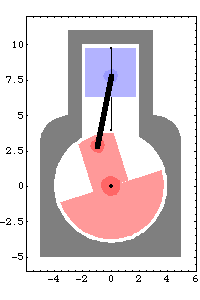
Undocumented Graphics GenerationThe following code generates the graphics in this section. These Modeler2D commands are defined in Chapter 3. 1.3 Basic 3D ModelIn this section the basic functionality of Modeler3D is demonstrated by building a kinematic model of a very simple mechanism. The mechanism is a slider-crank mechanism with two moving bodies, the crankshaft and the piston, identical to the mechanism that was modeled with Modeler2D in Section 1.2. Even though it is simply a planar mechanism, the slider-crank is modeled with Modeler3D to demonstrate the parallelism between Modeler2D and Modeler3D. 1.3.1 Mechanism FunctionThe Modeler3D package must be loaded before calling any Modeler3D functions. This loads the Modeler3D package. Here is a graphic of the 3D slider-crank model.
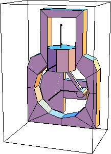
The following example analyzes the motion of a classic slider-crank mechanism. This mechanism is modeled with a simple and intuitive set of mechanical constraints that are representative of how such a problem would usually be modeled with Modeler3D. Body NumbersThe slider-crank mechanism consists of three bodies.
Body 1 is the ground body.
Body 2 is the crankshaft.
Body 3 is the piston.Each independent body in a Mech model must be given a unique positive integer body number. The choice of each body number is arbitrary except for the ground body, which must be body 1. These body numbers are used throughout a Mech model to reference each body. The ground body, which is stationary by definition, is used as the reference location and orientation for the rest of the model. All mechanism models must have some reference to the ground body to be adequately constrained.
To aid in the readability of the mechanism models created with Mech, it is customary to name each of the bodies in a mechanism, and then define each of these names to be equal to the integer body number of the body. Each body can then be referenced by name instead of by a number. Define body names to be used to reference each body. A real slider-crank mechanism would have a fourth body; the connecting rod between the crankshaft and the piston. However, in the kinematic model this entire part can be replaced by a simple distance constraint specifying that the crank pin and the piston pin are to be a constant distance apart. This technique decreases the overall size of the model. Local CoordinatesEach body in a mechanism model must have a local coordinate system attached to it. How to place this coordinate system on the body is up to the user and is based on the needs of the model. It is not necessary to place the local coordinate origin at the center of gravity of the body. The local coordinate system of each body is used to define points, lines, planes, and other features on the body that are then tied together to make the mechanical constraints.
The local coordinate system of the ground body is coincident with the global coordinate system. Therefore, the global coordinate system is referenced only through the ground body by specifying body 1. 1.3.2 3D BodiesGroundThe local coordinate system of the ground body originates at the center of the crankshaft. Five local point coordinates are used on the ground body.
P1 and P2 are two points that define the rotational axis of the crankshaft. P1 is at the global origin and P2 is on the positive Z axis.
P3 is a point on the positive X axis that is used (with point 1) to define a reference line to control the rotation of the crankshaft and the piston.
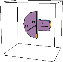
P4 and P5 are two points on the positive Y axis that are used to define the vertical translation line of the piston.Here is a graphic of the ground body. The point coordinates on the ground body are P1 {0, 0, 0}, P2 {0, 0, 5}, P3 {3, 0, 0}, P4 {0, 4, 0}, and P5 {0, 9, 0}.
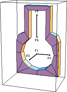
CrankshaftThe local coordinate system of the crankshaft originates at its rotational center. Three local point coordinates are used on the crankshaft.
P1 and P2 are two points that define the rotational axis of the crankshaft. P1 is on the local origin and P2 is on the positive local z axis.
P3 is a point on the local x axis that is used as the attachment point of the connecting rod and as a reference point to control the rotation of the crank.Here is a graphic of the crankshaft. The local point coordinates on the crankshaft are P1 {0, 0, 0}, P2 {0, 0, 5}, and P3 {3, 0, 0}.
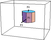
PistonThe local coordinate system on the piston originates at a point that is four units below the attachment point of the connecting rod. Thus, when the slider-crank mechanism is in its initial configuration, the local origin of the piston is coincident with the global origin. Three local point coordinates are used on the piston.
P1 is a point on the local y axis that is the attachment point of the connecting rod.
P2 is another point on the local y axis that is the other end of the translation line of the piston.Here is a graphic of the piston. The local point coordinates on the piston are P1 {0, 4, 0}, P2 {0, 6, 0}, and P3 {0, 4, 5}.
1.3.3 3D ConstraintsNow that the local point coordinates on each 3D body are defined, building the model is simply a matter of tying the points together with the correct mechanical constraints. Modeler3D provides a library of mechanical constraint objects that translate the desired physical conditions that are imposed on the model into mathematical equations. Constraint ObjectsFive constraint objects are used to model the slider-crank mechanism, constraining a total of 12 degrees of freedom (6 degrees of freedom for each moving body). Some 3D constraint objects. Note that the last character in the name of any Mech constraint object is an integer that specifies the number of degrees of freedom that it constrains.
The first argument to each constraint object, cnum, is the user-specified constraint number. This number is used to reference the constraint later in the modeling process, just as body numbers are used to reference specific bodies.
The point, vector, and axis arguments required by Modeler3D constraint objects are specified with Point, Vector, Line, Axis, and Plane objects, used in much the same manner as the built-in Mathematica graphics primitives, Point and Line. These objects are discussed in detail in Section 2.2. Building the ModelThe Modeler3D constraint objects used to model the physical relationships in the slider-crank model are as follows. A Revolute5 constraint forces the rotational axis of the crankshaft to be coincident with an axis on the ground body. This constrains five degrees of freedom: X, Y, and Z displacement and rotation about the global X or Y axes. The one degree of freedom left for the crankshaft is rotation about the global Z axis. The syntax of this constraint can be interpreted as, "Constrain a line on the ground body spanning from {0, 0, 0} to {0, 0, 5} to be coincident with a line on the crankshaft spanning from {0, 0, 0} to {0, 0, 5}, and constrain the origins of the two lines to be coincident."A ProjectedAngle1 constraint specifies the rotational orientation of the crankshaft. This constraint works by projecting two vectors onto a specified plane, and then specifying the angle between the two vectors. The crankshaft is now completely constrained. The syntax of this constraint can be interpreted as, "Constrain the counterclockwise direction angle of the vector {3, 0, 0} on the crankshaft to be crankangle units greater than the direction angle of the vector {3, 0, 0} on the ground body, when the two vectors are projected on a plane on the ground body defined by the three points {0, 0, 0}, {3, 0, 0}, and {0, 4, 0}."A Cylindrical4 constraint forces a vertical (+Y) line on the piston to be colinear with a vertical line on the ground body. This constrains four degrees of freedom, X and Z displacement of the piston, and X and Z axis rotation of the piston. The two degrees of freedom left are the pistons vertical translation in the cylinder and rotation of the piston in the cylinder.A RelativeDistance1 constraint forces an eccentric point on the crankshaft to lie five units distant from a point on the vertical axis of the piston. This models the length of the connecting rod. The syntax of this constraint can be interpreted as, "Constrain the absolute distance between a point {3, 0, 0} on the crankshaft and a point {0, 4, 0} on the piston to be equal to 5.0."An Orthogonal1 constraint forces a vector in the Z direction on the piston to be orthogonal to a vector in the X direction on the ground body. This constraint stops the piston from rotating in the cylinder, a function that would have been performed by the connecting rod in a real piston engine. This completes the constraint of the piston.The Modeler3D constraint objects are finally assembled into a mechanism model with SetConstraints. The fundamental model-building function. Here is the entire slider-crank model built in one step. SetConstraints returns Null. All of the mechanism equations generated by SetConstraints are stored internally in the Modeler3D private context. 1.3.4 Running the ModelA single command is used to solve the constraint equations and return the coordinates of each of the bodies the model. The fundamental model-solving function. This seeks a solution at crankangle = 0.
Out[8]= |  |
SolveMech returns the global coordinates of the origin of each body in the system. X2, Y2, and Z2 specify the location of the origin of body 2, the crankshaft.
Eo2, Ei2, Ej2, and Ek2 are the Euler generalized parameters specifying the angular orientation of the crankshaft. SolveMech returns a {Xn, Yn, Zn, Eon, Ein, Ejn, Ekn} set for each body in the system. For those unfamiliar with Euler parameters, suffice it to say that the four Euler parameters provide a numerically robust means of specifying the three degrees of freedom of the angular orientation of a body in 3D space. Values of {1, 0, 0, 0} for the four parameters, respectively, correspond to alignment with the global coordinate system. It is not necessary to have an understanding of the Euler parameters to utilize Modeler3D because postprocessing functions use the Euler parameters to generate more familiar output, such as the rotation of a body about an axis or the angle between two vectors. Euler parameters are discussed further in Chapter 4. Here is a graphic of the slider-crank model at the initial configuration.
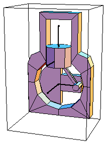
Not a very interesting solution! The solution at crankangle = 0 is for the local coordinate system of each body to be aligned with the global coordinate system. This is because the model was defined such as to have this perfect assembled configuration. The piston is defined such that its local origin lies at a point that is outside of the piston body. This point is coincident with the global origin when crankangle = 0. Note the 3-4-5 triangle formed by the crankshaft, piston, and connecting rod when crankangle = 0.
Advancing crankangle results in a more interesting solution. This seeks a solution at crankangle = 1/10 revolution.
Out[10]= |  |
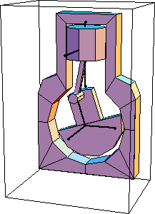
Now two of the Euler parameters of the crankshaft Eo2 and Ek2 have changed, and the vertical coordinate of the piston Y3 has increased to 2.13. All of the other coordinates have not changed, and never will, because of the specific function of this particular mechanism model. This seeks a solution at crankangle = 3/10 revolution.
Out[12]= |  |
Here is a graphic of the model at crankangle = 3/10 revolution.
Undocumented Graphics GenerationThe following code generates the graphics in this section. These Modeler3D commands are defined in Chapter 3.
|