8.1 Inertia PropertiesIn order for any inertial loads to exist in a mechanism model, the bodies of the mechanism must have nonzero inertia properties, mass and inertia. The inertia properties of the bodies in a model are defined in Mech body objects, and then added to the current model with the SetBodies command. 8.1.1 Body OptionsMech body objects are used to define specific properties of a body in a mechanism model. Properties are defined with options to the Body function. The body object builder. Two of the options for Body that are used for basic kinematic models are PointList and InitialGuess, which are discussed in Section 2.1. The remaining three options for Body are used to define the inertia properties of a body. 2D2D inertia property options for Body. 3D3D inertia property options for Body. Executing the Body function does not, in itself, have any affect on the current Mech model. The returned SysBody data objects must be added to the model with the SetBodies command. The body object processing function. 8.1.2 ExamplesTo use the 2D example mechanism of Section 1.2 in a dynamic analysis, inertia properties would be added with body objects and the SetBodies function. The crankshaft-piston mechanism used three Modeler2D bodies: the ground, crankshaft, and piston. This loads the Modeler2D package. Names are defined for each of the bodies in the model. For this example, it is assumed that the constraints of the crankshaft-piston model have already been defined as they were in Section 1.2.
There is no use in adding inertia properties to the ground body, as it cannot move, and therefore can sustain no inertial loads. The inertia properties of the crankshaft and piston are defined and added to the model. Here are the mass and inertia properties for the crankshaft and piston. The inertia properties must be incorporated into the model. Because the default setting for all options for Body is Automatic, which leaves the current values of properties unchanged, a single inertia property can be changed without affecting the rest of the model. An example is changing the location of the centroid of the piston without changing any other body properties. This moves the centroid of the piston only. Each of the inertia property options for Body can be interrogated to find the current settings of a body property. Inertia property functions. Here is the mass of the crankshaft.
Out[9]= |  |
8.1.3 Compound Inertia PropertiesThe centroidal inertia properties of a 3D body in a mechanism model must be determined before the dynamic reaction forces in a model can be found. For complex 3D bodies, the values of the moments and products of inertia can be quite difficult to determine manually. This problem is alleviated by the availability of 3D solid modeling systems that can generally calculate the inertia properties of any solid body that they are capable of modeling.
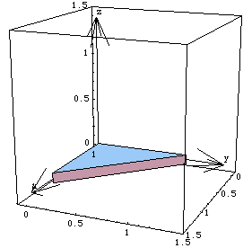
If the inertia properties of a body must be found manually, the body can be subdivided into several elementary geometrical components such as spheres, cylinders, or plates. Modeler3D provides several functions to aid in manipulating the inertia properties of a body or multiple bodies. These functions can make the task of determining the inertia properties of a slightly complex body more manageable. Utilities for manipulating 3D inertia properties. Inertia TransformationsThe following example takes the inertia properties of a triangular plate that are calculated in a noncentroidal reference frame and convert them to a centroidal frame. The plate is an isosceles right triangle with two one-unit sides. Triangular plate

The inertia properties of the plate, in the shown reference frame, can be integrated directly or found in an engineering or mathematics handbook. Here are the basic inertia properties of the plate.
Out[10]= |  |
iyy is known by symmetry.
Out[12]= |  |
Out[13]= |  |
iyz and izx are zero because the plate has zero thickness. The location of the centroid of the plate can also be found by direct integration, knowing that the mass of the plate is 1/2 because the density of the plate is one unit mass per unit area. Here are the mass and centroid location.
Out[16]= |  |
This loads the Modeler3D package. To use the ParallelAxis function to transform noncentroidal inertia properties into a centroidal reference frame, instead of vice versa, the vector from the centroid to the origin of the noncentroidal frame is specified in the centroidal reference frame coordinates, and a negative mass is specified. Note that the sign of the centroid vector is irrelevant, but it must be given in the correct reference frame if there is any relative rotation between the frames.
ParallelAxis returns the centroidal inertias {Ixx, Iyy, ...} that are reduced in magnitude relative to the noncentroidal properties. Here are the centroidal inertia properties of the plate.
Out[18]= |  |
The principal axes of inertia of the plate can be found with the PrincipalAxes function. Note that the list of the three principal axes of inertia forms the rotation matrix from the local reference frame of the inertia properties to the principal reference frame. Here are the principal inertias and axes of the plate.
Out[19]= |  |
This rotates the original inertia matrix into the principal frame.
Out[20]= |  |
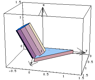
Composite BodiesThe CompositeInertia function is used to add the inertia properties of several bodies together and return the centroidal inertia properties of their superset. In the following example, the inertia properties of the triangular plate are added to the inertia properties of a cylinder that is attached to the plate and rotated through a 30-degree angle about the local x axis, as shown below. The radius of the cylinder is 0.25 and the length is 1 unit. The bottom surface of the cylinder is coplanar with the local x axis of the plate. A composite body

The centroidal inertia properties of a cylinder in an axial reference frame can be found in an engineering manual. These properties have been determined and are given in the following example. Here are the inertia properties of the cylinder.
Out[22]= |  |
Out[23]= |  |
Out[24]= |  |
CompositeInertia can now be used to combine the inertia properties of the plate and the cylinder into one set of centroidal inertia properties. Note that the optional rotation argument is used for the cylinder since the reference frame in which its inertia properties were calculated was not aligned with the local reference frame. Here are the inertia properties of the combined thin plate and cylinder.
Out[25]= |  |
2D Inertia FunctionsModeler2D also provides two inertia transformation functions that parallel those in Modeler3D, although the calculations they perform are trivial by comparison. Utilities for manipulating 2D inertia properties. Undocumented Graphics Generation
|