Room Heating
This application example will explore room heat distribution as a combined SystemModel and partial differential equation (PDE) model. The coupling will be unidirectional, as the System Modeler model will be used to drive the PDE analysis. In a first step, System Modeler’s "Thermal College Virtual Lab" is used to explore a virtual model of a room. In a second step, a PDE model is created that will compute the actual heat distribution in the room.
The System Modeler part of this application example being based on a virtual lab offers the benefit of a well-documented system model. If this is a first exposure to System Modeler models, going through the "Thermal College Virtual Lab" is advised to gain an understanding of how System Modeler works.
Lumped Room Model
In this section, the room model that was created with System Modeler is brought into Wolfram Language. In the next step, different setting are applied to understand how they affect the room energy dynamics.
Import Lumped System Model
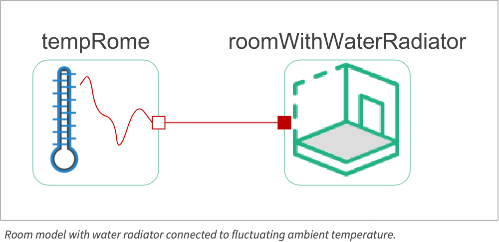
To use a specific model, in this case the "RoomModelRome", that model is selected from the model library. The model can be opened by checking its children.
SystemModel["DocumentationExamples.Simulation.RoomHeating", "Children"]model = SystemModel["DocumentationExamples.Simulation.RoomHeating.RoomModelRome"];
model["Diagram"]Now that the model is loaded, it can be simulated. This is done using SystemModelSimulate.
sim = SystemModelSimulate[model]The result is a SystemModelSimulationData instance that contains all the simulation results of interest.
SystemModelPlot[sim]Other variables can also be plotted by specifying the correct variable name.
SystemModelPlot[sim, {"roomWithWaterRadiator.room.temp"}]Varying Outside Temperature
The room behavior is analyzed with time-dependent temperature data. The model has some predefined temperature data as a function of time ![]() in seconds.
in seconds.
SystemModelPlot[sim, {"tempRome.port.T"}]Now test the model for the varying spring temperature.
Since during spring the outside temperature is around the reference temperature of 20 °C, the radiator is mostly in the OFF state. It is switched ON during the evening, when the temperature goes below the reference temperature.
Manipulate[
	SystemModelPlot[SystemModelSimulate["CollegeThermalFEM_MSL4.RoomHeating.Exercises.RoomModelRome", 36000, <|"ParameterValues" -> {"heatSupplied" -> x1, "heatCapacityRoom" -> x2 * 1000, "roomRefTemp" -> x3}|>], ImageSize -> Medium, AxesLabel -> {"Time[s]", "Temp[°C]"}], {{x2, 40, "Heat capacity of the room [kJ/K]"}, Row[{Slider[#, {0.1, 100, 1}, ContinuousAction -> False], Spacer[5], #}]&}, {{x3, 20, "Room reference temperature [°C]"}, Row[{Slider[#, {0, 30, 1}, ContinuousAction -> False], Spacer[5], #}]&}, {{x1, 1200, "Power of heat source [W]"}, Row[{Slider[#, {0, 5000, 1}, ContinuousAction -> False], Spacer[5], #}]&}, ContinuousAction -> False, SynchronousUpdating -> False, SynchronousInitialization -> False, Initialization :> Import[FileNameJoin[...]]]
PDE Room Model
In this section, a 2D model of the room is built. The model is then used to study how temperature changes across the room by using values for the boundary conditions that come from the System Modeler model.
The idea is to find the heat distribution in the room that ensures an average temperature of 20 degrees in the room. For this, a parametric partial differential equation is set up where a parameter models the heat generated by the heater. For a given heater value, a temperature distribution in the room can then be found. The integration over this temperature distribution will give an average temperature in the room for a given value of the heater. This will allow you to find the value of the heater such that the average temperature in the room is 20 degrees.
Needs["NDSolve`FEM`"]Heat Transfer Model Setup
One possibility to model the heat distribution in the room is to use a heat transfer equation and use a partial differential equation model to describe the room. The room will be a simple rectangular geometry.
The heat transfer PDE is given as:
The dependent variable in the heat equation is the temperature ![]() , which varies with time
, which varies with time ![]() and position
and position ![]() . The partial differential equation (PDE) model describes how thermal energy is transported over time in a medium with density
. The partial differential equation (PDE) model describes how thermal energy is transported over time in a medium with density ![]() and specific heat capacity
and specific heat capacity ![]() . The specific heat capacity is a material property that specifies the amount of heat energy that is needed to raise the temperature of a substance with unit mass by one degree Kelvin.
. The specific heat capacity is a material property that specifies the amount of heat energy that is needed to raise the temperature of a substance with unit mass by one degree Kelvin.
Besides the time derivative part, the PDE is made up of several components. First and foremost, there is a diffusive term: ![]() with a thermal conductivity
with a thermal conductivity ![]() .
.
More information about modeling with the heat transfer equation can be found in the Heat Transfer monograph.
Model Parameter Setup
The goal is to find a steady-state temperature distribution of the room. This means that the temperature-dependent terms can be dropped, arriving at:
vars = {T[x, y], {x, y}}Set up a rectangular domain with a width of 4 [m] and a length of 4 [m] to model the room. A radiator is positioned close to the wall.
width = 4;
length = 4;
Ωroom = Rectangle[{0, 0}, {length, width}];
Ωradiator = Rectangle[{1, 1 / 10}, {3, 3 / 20}];
Ω = RegionDifference[Ωroom, Ωradiator];
RegionPlot[Ω]
Next, create a mesh of the room. Note that the radiator is to be a part of the mesh. The region of the radiator is used as the position for the energy source ![]() .
.
mesh = ToElementMesh[Ω, "RegionHoles" -> None]mesh["Wireframe"]To make use of specific material parameters in the equation, the relevant data is extracted from the ThermodynamicData.
In this model, the focus is on the temperature distribution within the room, with air assumed as the medium. The thermal conductivity of air is required for the heat transfer PDE model. The value of the room medium's thermal conductivity, however, was not required for the System Modeler model. There, the thermal conductivity of the walls was utilized in its computation. This means that the thermal conductivity of the room's medium air was not set in the system model, and it is set here.
Subscript[k, air] = ThermodynamicData["Air", "ThermalConductivity"]pars = <|"ThermalConductivity" -> Subscript[k, air]|>Now comes the crucial step where a parametric heat source, the radiator, is defined. For all spatial coordinates that are within the subdomain of the radiator, a heat source of ![]() is used. Outside of the radiator, there is 0 heat generated.
is used. Outside of the radiator, there is 0 heat generated.
rmf = RegionMember[Ωradiator];
pars["HeatSource"] = With[{rmf = rmf}, Piecewise[{{Qg, rmf[{x, y}]}}, 0]]
Next, specify the boundary conditions for the four walls. Because the system model is a transient model, a specific time at which to extract the data needs to be chosen—on this case, the time ![]() of the System Modeler simulation time.
of the System Modeler simulation time.
systemModelTime = 30000;srfTemp = sim[{"roomWithWaterRadiator.room.temp"}, systemModelTime][[1]]Subscript[Γ, wall] = HeatTemperatureCondition[x == 0 || x == length || y == 0 || y == width, vars, pars, <|"SurfaceTemperature" -> srfTemp|>]pde = {HeatTransferPDEComponent[vars, pars] == 0, Subscript[Γ, wall]}Now all components to set up the parametric function are available.
pfun = ParametricNDSolveValue[pde, T, {x, y}∈mesh, Qg]To get a better understanding of how the model behaves, the model is probed with a somewhat random value for the heat source.
Tfun = pfun[200]Show[
ContourPlot[Tfun[x, y], {x, y}∈Ω, ...],
Graphics[RegionBoundary[Ω]]
]The average value of the room temperature for a specific ![]() value is what is of interest. For this, write a helper function average.
value is what is of interest. For this, write a helper function average.
average[Qg_ ? NumericQ] := Module[{Tfun},
	Tfun = pfun[Qg];
	NIntegrate[Tfun[x, y], {x, y}∈mesh] / Area[Ω]
]average[200]As a last step, the value of ![]() that gives an average room temperature of 20 degrees is sought.
that gives an average room temperature of 20 degrees is sought.
root = FindRoot[average[Qg] == 20, {Qg, 200}]TfunFinal = pfun[Qg] /. rootShow[ContourPlot[TfunFinal[x, y], {x, y}∈Ω, ...],
Graphics[RegionBoundary[Ω]]]Going from a lumped model to a PDE can be tricky, since the lumped model makes assumptions that can not be recovered later but are needed for the PDE model. For example, the temperatures of the radiator, the room and the interior walls are all the same in the lumped scenario, which does not reflect reality.