WOLFRAM SYSTEM MODELER
MixerMixer to convert force and moments to the propeller forces |
|
Diagram
Wolfram Language
In[1]:=
SystemModel["Aircraft.Utilities.Mixer"]
Out[1]:=
Information
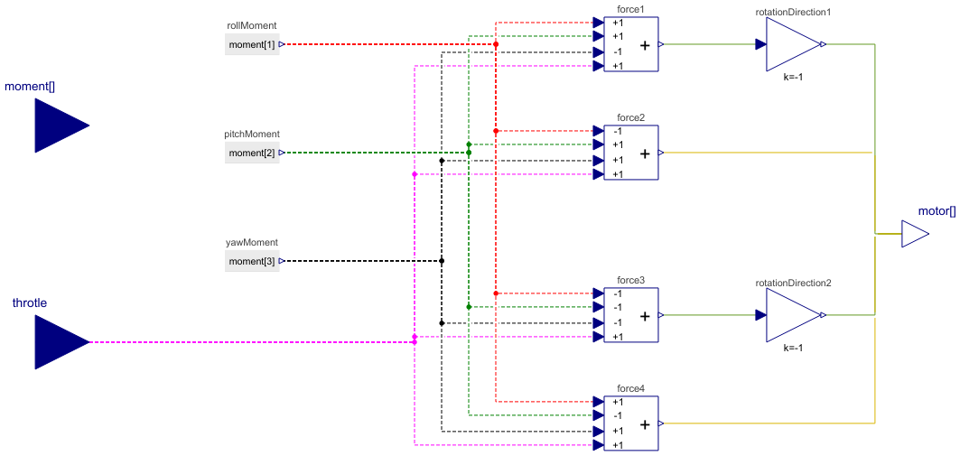
The Mixer block is employed to distribute forces and moments to each DC motor of the quadrotor. Its inputs include the throttle force and moment change commands originating from the controllers, and its outputs are the voltage commands for the DC motors. Within the mixer, an Add4 summation block is used to appropriately distribute the forces and moments, thereby achieving the desired quadrotor motion.
Figure 1 shows the mechanism of the change in rotation speed of the propellers to get the specific rotational motion. A positive roll motion can be obtained by increasing the rotaion speed of the left propellers (1 & 4) and the same amount of the deacrease in rotation speed of the other two propellers (2 and 3).we can get this change in the roll angle by introducing positive contribution of the roll signal in the first and fourth Add4 component, denoted as force1 and force2 in this model, and negative contribution of the roll signal in the second and third Add4 component. A positive pitch results from generating a positive lift increament of the front propellers (1 & 2) which is the result of the faster rotation of the front propellers and negative force increament of the back propellers (3 & 4). Yaw motion comes from the speeding up the rotation speed of the green diagonal pair of the propellers and solwing down the rotation speed of the yellow pair. For a positive altitude change (throttle command) the rotation speed of all propellers should increase for the same amount and negative altitude change needs a decrese of the rotation speed of the all propellers.


Therefore, the force summation breakdown is as follows:
force 1: + Roll + Pitch + Yaw + Thottle
force 2: - Roll + Pitch - Yaw + Thottle
force 3: - Roll - Pitch + Yaw + Thottle
force 4: +Roll - Pitch - Yaw + Thottle
The conversion gains are responsible for altering the rotation direction of the diagonal pairs of the quadrotor, where propellers 1 and 3 (the green pair) rotate clockwise, while propellers 2 and 4 (the yellow pair) rotate counter-clockwise.
Connectors (3)
| motor |
Type: RealOutput[4] Description: Vector of the voltage command of the ectric motor |
|
|---|---|---|
| moment |
Type: RealInput[3] Description: Vector of the moment command |
|
| throtle |
Type: RealInput Description: Throtle command |
Components (9)
| rotationDirection2 |
Type: Gain Description: Change rotation of the propeller to clockwise direction |
|
|---|---|---|
| force1 |
Type: Add4 Description: Force summation of the first electric motor |
|
| force2 |
Type: Add4 Description: Force summation of the second electric motor |
|
| force3 |
Type: Add4 Description: Force summation of the third electric motor |
|
| force4 |
Type: Add4 Description: Force summation of the fourth electric motor |
|
| rotationDirection1 |
Type: Gain Description: Change rotation of the propeller to clockwise direction |
|
| rollMoment |
Type: RealExpression Description: Roll moment command (L) |
|
| pitchMoment |
Type: RealExpression Description: Pitch moment command (M) |
|
| yawMoment |
Type: RealExpression Description: Yaw moment command (N) |
Used in Examples (1)
|
Aircraft.Examples Compare the impact of two types of controller structures on the motion of the quadrotor |