WOLFRAM SYSTEM MODELER
AccumulatorChargingCircuitExample circuit with an unloading relief valve and an accumulator |
|
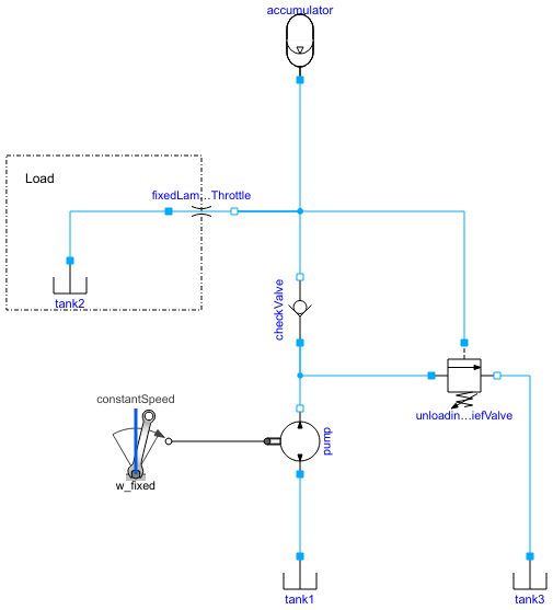
Diagram
Wolfram Language
In[1]:=
SystemModel["Hydraulic.Examples.Accumulators.AccumulatorChargingCircuit"]
Out[1]:=
Information
This example shows how an unloading relief valve can be used to limit maximum pressure and unload the pump when the desired accumulator pressure is reached.
Fig. 1 shows how the accumulator pressure builds up until a certain limit is reached. Fig. 2 shows how the mass flow rate through the relief valve increases when the pressure limit has been reached.
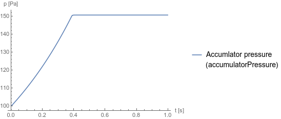
Fig. 1 Accumulator pressure
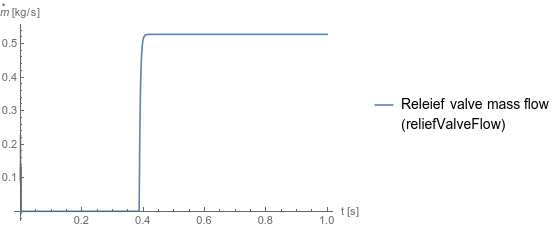
Fig. 2 Mass flow through the unloading relief valve
Fig. 1 shows how the accumulator pressure builds up until a certain limit is reached. Fig. 2 shows how the mass flow rate through the relief valve increases when the pressure limit has been reached.
Fig. 1 Accumulator pressure
Fig. 2 Mass flow through the unloading relief valve
Reference
Industrial Hydraulics Manual, 5th ed., Maumee, OH: Eaton Hydraulics Training Services, 2008 p. 284.Parameters (6)
| medium |
Value: Oil() Type: Medium Description: Medium in the component |
|---|---|
| pMin |
Value: 30000000.0 Type: Pressure (Pa) Description: Pressure when valve starts to open (unloadingReliefValve.pMin) |
| pMax |
Value: 31000000.0 Type: Pressure (Pa) Description: Pressure when valve is fully open (unloadingReliefValve.pMax) |
| w_fixed |
Value: 157 Type: AngularVelocity (rad/s) Description: Fixed speed (constantSpeed.w_fixed) |
| G |
Value: 9.999999999999999e-12 Type: ConductanceOfLaminarResistance (m³/(s⋅Pa)) Description: Conductance of laminar resistance (fixedLaminarThrottle.G) |
| gamma |
Value: 1.404 Type: Real Description: Polytropic index of gas, default value 1.404 for nitrogen gas (accumulator.gamma) |
Components (10)
| medium |
Type: Medium Description: Medium in the component |
|
|---|---|---|
| accumulator |
Type: GasChargedAccumulator Description: Hydraulic accumulator |
|
| tank1 |
Type: Tank Description: Simple tank with constant pressure |
|
| tank2 |
Type: Tank Description: Simple tank with constant pressure |
|
| pump |
Type: Pump Description: Model of a pump with fixed displacement and volumes |
|
| constantSpeed |
Type: ConstantSpeed Description: Constant speed, not dependent on torque |
|
| checkValve |
Type: CheckValve Description: Check valve with lumped volumes |
|
| unloadingReliefValve |
Type: UnloadingReliefValve Description: Unloading relief valve, controlled by the pressure difference between the ports |
|
| tank3 |
Type: Tank Description: Simple tank with constant pressure |
|
| fixedLaminarThrottle |
Type: FixedLaminarThrottle Description: Laminar restriction using conductance |