WOLFRAM SYSTEM MODELER
CheckValveCheck valve with lumped volumes |
|
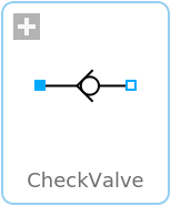
Diagram

Wolfram Language
In[1]:=
SystemModel["Hydraulic.Valves.DirectionalControl.CheckValve"]
Out[1]:=
Information
This is a model of a check valve with lumped volumes. If the pressure difference is higher than pMin, the valve begins to open; when the pressure difference has reached pMax, the valve is completely open. If the pressure is less than pMin, the valve is closed and has only leakage flow. This behavior makes the component only allow flow in one direction. The ball is modeled with a spool with first-order dynamics; see SpoolH.
Implementation
This valve basically consists of an orifice controlled by a spool.Reference
Industrial Hydraulics Manual, 5th ed., Maumee, OH: Eaton Hydraulics Training Services, 2008 p. 184.Parameters (8)
| medium |
Value: Oil() Type: Medium Description: Medium in the component |
|---|---|
| V |
Value: 0.0001 Type: Volume (m³) Description: Volume of control valve |
| Gleak |
Value: 9.999999999999999e-21 Type: PressureDependentLeakage (m³/(s⋅Pa)) Description: Leakage between ports |
| A |
Value: 0.0001 Type: Area (m²) Description: Opening area when opened |
| Cd |
Value: 0.62 Type: Real Description: Coefficient of discharge for the opening |
| pMax |
Value: 100000.0 Type: Pressure (Pa) Description: Pressure when valve is fully open |
| pMin |
Value: 100 Type: Pressure (Pa) Description: Pressure when valve starts to open |
| t1 |
Value: 0.001 Type: Time (s) Description: Time constant for first-order system |
Connectors (2)
Components (4)
| medium |
Type: Medium Description: Medium in the component |
|
|---|---|---|
| checkValve |
Type: CheckValve Description: Static check valve |
|
| volume_a |
Type: Volume Description: Fixed volume with fluid storage |
|
| volume_b |
Type: Volume Description: Fixed volume with fluid storage |
Used in Examples (5)
|
Hydraulic.Examples.Accumulators Example circuit with an unloading relief valve and an accumulator |
|
|
Hydraulic.Examples.Accumulators Example circuit with automatic discharge of an accumulator |
|
|
Hydraulic.Examples.Accumulators Example circuit with an accumulator and cylinder |
|
|
Hydraulic.Examples.FlowControl Example circuit with meter-out flow control |
|
|
Hydraulic.Examples.MultipleActuators Example circuit with a sub-circuit operating at a reduced pressure |
Used in Components (3)
|
Hydraulic.Valves.FlowControl Assembly with a restriction and check valve |
|
|
Hydraulic.Valves.FlowControl Counterbalance valve, allowing flow in one direction. The pilot port can be used to allow flow in the other direction. |
|
|
Hydraulic.Valves.FlowControl Brake valve, allowing flow in one direction. The pilot port can be used to allow flow in the other direction. |