WOLFRAM SYSTEM MODELER
AccumulatorAndCylinderCircuitExample circuit with an accumulator and cylinder |
|
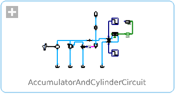
Diagram

Wolfram Language
In[1]:=
SystemModel["Hydraulic.Examples.Accumulators.AccumulatorAndCylinderCircuit"]
Out[1]:=
Information
This example shows how a compound relief valve can be used to limit maximum pressure and unload the pump when the desired accumulator pressure is reached. When this happens, a pressure switch triggers a valve that ventilates the compound relief valve. When the load moves, the accumulator discharges and eventually the pressure switch flips back. This allows the pump flow into the circuit again.
Fig. 1 shows the load position. Fig. 2 shows the state of the pressure switch. In Fig. 3 you can see how the accumulator pressure initially builds up, drops during the cylinder movement, and finally builds up again after the cylinder stopped.
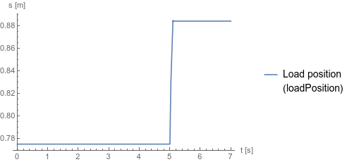
Fig. 1 Load position
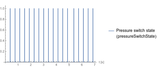
Fig. 2 State of the pressure switch
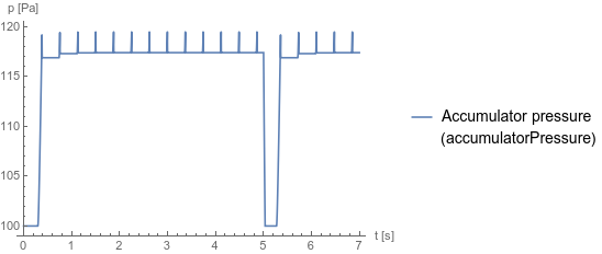
Fig. 3 Accumulator pressure
Fig. 1 shows the load position. Fig. 2 shows the state of the pressure switch. In Fig. 3 you can see how the accumulator pressure initially builds up, drops during the cylinder movement, and finally builds up again after the cylinder stopped.
Fig. 1 Load position
Fig. 2 State of the pressure switch
Fig. 3 Accumulator pressure
Reference
Industrial Hydraulics Manual, 5th ed., Maumee, OH: Eaton Hydraulics Training Services, 2008 p. 474.Parameters (2)
Components (20)
| medium |
Type: Medium Description: Medium in the component |
|
|---|---|---|
| accumulator |
Type: GasChargedAccumulator Description: Hydraulic accumulator |
|
| tank1 |
Type: Tank Description: Simple tank with constant pressure |
|
| pump |
Type: Pump Description: Model of a pump with fixed displacement and volumes |
|
| constantSpeed |
Type: ConstantSpeed Description: Constant speed, not dependent on torque |
|
| checkValve |
Type: CheckValve Description: Check valve with lumped volumes |
|
| tank2 |
Type: Tank Description: Simple tank with constant pressure |
|
| compoundReliefValve |
Type: CompoundReliefValve Description: Pilot-operated relief valve |
|
| ventilationValve |
Type: DCVE22 Description: Electrically actuated proportional valve with two ports and two states |
|
| oneWayFlowControlValve |
Type: OneWayFlowControlValve Description: Assembly with a restriction and check valve |
|
| controlValve |
Type: DCVE43ClosedCenter Description: Electrically actuated proportional control valve with four ports and three states |
|
| tank4 |
Type: Tank Description: Simple tank with constant pressure |
|
| tank3 |
Type: Tank Description: Simple tank with constant pressure |
|
| stepStartMovement |
Type: Step Description: Generate step signal of type Real |
|
| cylinderDouble |
Type: CylinderDouble Description: Double cylinder model |
|
| mass |
Type: Mass Description: Sliding mass with inertia |
|
| positionSensor |
Type: PositionSensor Description: Ideal sensor to measure the absolute position of flange |
|
| stepStopMovement |
Type: Step Description: Generate step signal of type Real |
|
| pressureSwitch |
Type: PressureSwitch Description: Pressure sensor with a Boolean output that is true if the absolute pressure exceeds a threshold |
|
| booleanToReal |
Type: BooleanToReal Description: Convert Boolean to Real signal |