WOLFRAM SYSTEM MODELER
ControlledOrificeControlled restriction |
|
Wolfram Language
In[1]:=
SystemModel["Hydraulic.Restrictions.ControlledOrifice"]
Out[1]:=
Information
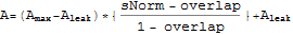
This is a model of a controlled restriction. The opening area A is controlled with a signal sNorm, normalized between -1 and +1. The area remains at  until sNorm has exceeded the overlap parameter. When sNorm reaches 1, the area A equals the parameter
  . When sNorm is between overlap and 1, the area A follows the equation below:
The flow through the orifice is proportional to the square root of the pressure drop:

where
until sNorm has exceeded the overlap parameter. When sNorm reaches 1, the area A equals the parameter . When sNorm is between overlap and 1, the area A follows the equation below: The flow through the orifice is proportional to the square root of the pressure drop:
where
| A | : | Opening area | |
 | : | Maximum opening area | |
 | : | Minimum opening area | |
| sNorm | : | Normalized control signal | |
| overlap | : | The orifice does not start to open until sNorm has exceeded this value | |
 | : | Mass flow rate | |
 | : | Fluid density | |
 | : | Discharge coefficient | |
 | : | Pressure difference between ports a and b |
Implementation
The flow equation is linearized for pressure differences near zero to increase numerical stability.Reference
K. Gieck and R. Gieck, Engineering Formulas, 7th ed., Germering, Germany: Gieck Publishing, 1997 p. N7.Parameters (7)
| medium |
Value: Oil() Type: Medium Description: Medium in the component |
|---|---|
| Gleak |
Value: 1e-020 Type: PressureDependentLeakage (m³/(s⋅Pa)) Description: Conductance of closed valve |
| Aleak |
Value: (Gleak * ReCr * medium.nu * medium.rho * sqrt(Modelica.Constants.pi) / (4 * Cd ^ 2)) ^ (2 / 3) Type: Area (m²) Description: Minimum opening area |
| AMax |
Value: 0.0001 Type: Area (m²) Description: Maximum opening area |
| Cd |
Value: 0.62 Type: Real Description: Coefficient of discharge for the opening |
| ReCr |
Value: 12 Type: Real Description: Critical Reynolds number |
| overlap |
Value: 0 Type: Length (m) Description: Normalized position when the opening is closed |
Connectors (3)
Components (1)
| medium |
Type: Medium Description: Medium in the component |
|---|
Used in Components (23)
|
Hydraulic.Valves.DirectionalControl.Internal.States Basic building block for directional control valves |
|
|
Hydraulic.Valves.DirectionalControl.Internal.States Basic building block for directional control valves |
|
|
Hydraulic.Valves.DirectionalControl.Internal.States Basic building block for directional control valves |
|
|
Hydraulic.Valves.DirectionalControl.Internal.States Basic building block for directional control valves |
|
|
Hydraulic.Valves.DirectionalControl.Internal.States Basic building block for directional control valves |
|
|
Hydraulic.Valves.DirectionalControl.Internal.States Basic building block for directional control valves |
|
|
Hydraulic.Valves.DirectionalControl.Internal Partial valve with two ports and two states |
|
|
Hydraulic.Valves.DirectionalControl.Internal Partial valve with three ports and two states |
|
|
Hydraulic.Valves.DirectionalControl.Internal Partial valve with three ports and two states |
|
|
Hydraulic.Valves.DirectionalControl.Internal Partial valve with six ports and three states |
|
|
Hydraulic.Valves.DirectionalControl.Internal Static check valve |
|
|
Hydraulic.Valves.DirectionalControl.Internal Static shuttle valve |
|
|
Hydraulic.Valves.DirectionalControl.Internal Static dual pressure valve |
|
|
Hydraulic.Valves.DirectionalControl.Internal Static pilot-operated check valve |
|
|
Hydraulic.Valves.FlowControl.Internal Static flow fuse valve (normally open, closes on excess flow) |
|
|
UnloadingReliefValveWithReversedPilot Hydraulic.Valves.FlowControl.Internal Static unloading relief valve with pilot ratio applied to port_a |
|
|
Hydraulic.Valves.FlowControl Controlled restriction |
|
|
Hydraulic.Valves.PressureControl.Internal Static pressure relief valve |
|
|
Hydraulic.Valves.PressureControl.Internal Static pressure reducing valve |
|
|
Hydraulic.Valves.PressureControl.Internal Static unloading relief valve |
|
|
PressureCompensatingValveNormallyOpen Hydraulic.Valves.PressureControl.Internal Static pressure compensating valve |
|
|
PressureCompensatingValveNormallyClosed Hydraulic.Valves.PressureControl.Internal Static pressure compensating valve |
|
|
Hydraulic.LiquidContainers Model of a tank with environment pressure at inlet, hydrostatic pressure at the bottom, and an outlet orifice |